Sign In
Upload
Download
Table of Contents
Contents
Add to my manuals
Delete from my manuals
Share
URL of this page:
HTML Link:
Bookmark this page
Add
Manual will be automatically added to "My Manuals"
Print this page
×
Bookmark added
×
Added to my manuals
Manuals
Brands
D-Link Manuals
Ethernet switch
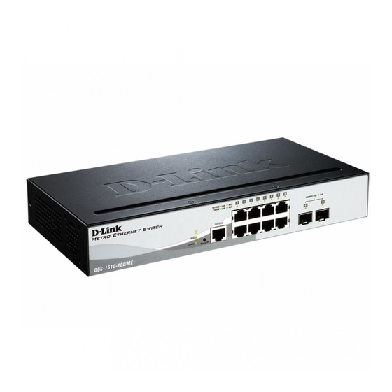
DGS-1510-10L/ME
Hardware installation manual
D-Link DGS-1510-10L/ME Hardware Installation Manual
Dgs-1510/me series, metro
Hide thumbs
1
2
3
Table Of Contents
4
5
6
7
8
9
10
11
12
13
14
15
16
17
18
19
20
21
22
23
24
25
26
27
28
29
30
31
32
33
34
35
36
37
38
39
40
41
42
43
44
45
46
47
48
49
50
51
52
53
54
55
56
57
58
59
60
61
62
63
64
65
66
67
page
of
67
Go
/
67
Contents
Table of Contents
Bookmarks
Table of Contents
Table of Contents
Intended Readers
Typographical Conventions
Notes and Cautions
Safety Instructions
Safety Precautions
General Precautions for Rack-Mountable Products
Protecting against Electrostatic Discharge
Chapter 1 Introduction
Switch Description
Package Contents
Features
Front Panel Components
Ports
LED Indicators
Rear Panel Components
Side Panel Components
Smart Fans
Chapter 2 Installation
Installation Guidelines
Installing the Switch Without a Rack
Installing the Switch in a Standard 19" Rack
Installing Transceivers into the Transceiver Ports
Power on (AC Power)
Power Failure (AC Power)
Installing the Power Cord Clip
Power on (DC Power)
Installing the Redundant Power Supply (RPS)
Connecting the RPS to the RPS Port
Installing the RPS into a Rack-Mount Chassis
Chapter 3 Connecting the Switch
Switch to End Node
Switch to Another Switch
Connecting to a Network Backbone or Server
Chapter 4 Introduction to Switch Management
Management Options
Connecting to the Console Port
Connecting to the Switch for the First Time
Creating a User Account
Configuring the IP Address
SNMP Settings
Traps
Management Information Base (MIB)
Chapter 5 Web-Based Switch Configuration
Introduction
Logging into the Web UI
Web-Based User Interface (Web UI)
Areas of the Web UI
Web Pages
Appendix A - Technical Specifications
General
Physical and Environmental
Performance
LED Indicators
Port Functions
Appendix B - Cables and Connectors
Ethernet Cable
Console Cable
Redundant Power Supply (RPS) Cable
Warranties & Technical Support
Advertisement
Quick Links
1
Table of Contents
2
Switch Description
3
Logging into the Web Ui
Download this manual
Table of
Contents
Previous
Page
Next
Page
1
2
3
4
5
Advertisement
Table of Contents
Need help?
Do you have a question about the DGS-1510-10L/ME and is the answer not in the manual?
Ask a question
Questions and answers
Related Manuals for D-Link DGS-1510-10L/ME
Ethernet switch D-Link DGS-1510-28XS/ME Hardware Installation Manual
Dgs-1510/me series, metro (67 pages)
Ethernet switch D-Link DGS-1510-52L/ME Hardware Installation Manual
Dgs-1510/me series, metro (67 pages)
Ethernet switch D-Link des-1228/ME Hardware Installation Manual
Layer 2 managed metro ethernet switch (53 pages)
This manual is also suitable for:
Dgs-1510-20l/me
Dgs-1510-28l/me
Dgs-1510-28lp/me
Dgs-1510-28x/me
Dgs-1510-28xmp/me
Dgs-1510-28xs/me
...
Show all
Dgs-1510-52l/me
Dgs-1510-52x/me
Table of Contents
Print
Rename the bookmark
Delete bookmark?
Delete from my manuals?
Login
Sign In
OR
Sign in with Facebook
Sign in with Google
Upload manual
Upload from disk
Upload from URL


Need help?
Do you have a question about the DGS-1510-10L/ME and is the answer not in the manual?
Questions and answers