Table of Contents
Advertisement
Advertisement
Table of Contents

Summarization of Contents
Safety and Regulatory Compliance
FCC Warning
Compliance with FCC digital device limits for commercial environments.
CE Mark Warning
Advisory for Class A products in domestic settings.
VCCI Warning
Japanese advisory on potential radio interference.
BSMI Notice
Taiwan BSMI Class A compliance notice.
Class 1 Laser Product Safety
Crucial safety warning for laser emitting devices.
Optical Module Compliance
Regulatory compliance for SFP, XENPAK, XFP modules.
Document Conventions
Intended Readers
Description of the target audience for the manual.
Typographical Conventions
Explains formatting used in the document.
Notes and Cautions
Defines symbols for important information.
Safety Instructions
Outlines general safety guidelines for device use.
Electrostatic Discharge Protection
Electrostatic Discharge Protection
Methods to prevent ESD damage to components.
Chapter 1 Introduction
Switch Description
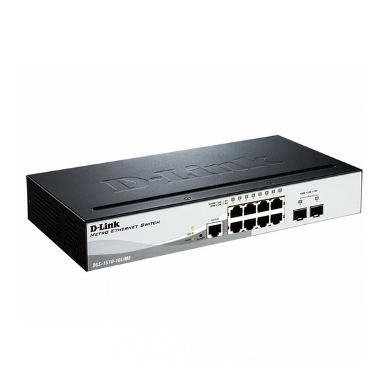
Overview of the DGS-1510/ME Series switches.
Package Contents
Lists items included in the switch package.
Features
Highlights significant capabilities of the switch.
Front Panel Components
Describes ports and indicators on the front of the switch.
Ports
Details the types of ports available on the front panel.
LED Indicators
Explains the function of various LED indicators.
Rear Panel Components
Describes components on the rear of the switch.
Side Panel Components
Details heat vents, fans, and mounting holes on the sides.
Smart Fans
Explains the behavior of the switch's cooling fans.
Chapter 2 Installation
Installation Guidelines
General recommendations for installing the switch.
Installing the Switch without a Rack
Steps for placing the switch on a flat surface.
Installing the Switch in a Standard 19" Rack
Instructions for mounting the switch in a rack.
Installing Transceivers into the Transceiver Ports
Guide for inserting SFP/SFP+ transceivers.
Power On (AC Power)
Procedure for powering the switch using AC power.
Power Failure (AC Power)
Precautions during AC power interruptions.
Installing the Power Cord Clip
How to secure the power cord.
Power On (DC Power)
Steps for powering the switch using DC power.
Installing the Redundant Power Supply (RPS)
Information on using an optional RPS.
Connecting the RPS to the RPS Port
How to connect the RPS to the switch.
Installing the RPS into a Rack-mount Chassis
Instructions for installing RPS in a chassis.
Chapter 3 Connecting the Switch
Switch to End Node
How to connect individual devices to the switch.
Switch to another Switch
How to connect multiple switches together.
Connecting to a Network Backbone or Server
Connecting to core network infrastructure.
Chapter 4 Introduction to Switch Management
Management Options
Overview of ways to manage the switch.
Connecting to the Console Port
Setting up a direct serial connection for management.
Connecting to the Switch for the First Time
Initial connection and boot procedure.
Creating a User Account
Steps to create login credentials for management.
Configuring the IP Address
How to assign an IP address to the switch.
SNMP Settings
Configuration for Simple Network Management Protocol.
Chapter 5 Web-based Switch Configuration
Introduction
Overview of managing the switch via a web browser.
Logging into the Web UI
Steps to access the switch's web interface.
Web-based User Interface (Web UI)
Description of the Web UI's layout.
Areas of the Web UI
Explains the different sections of the Web UI.
Web Pages
Details the main folders within the Web UI navigation.
Appendix A – Technical Specifications
General
General technical specifications like standards and data rates.
Physical and Environmental
Physical dimensions, power, and fan details.
Performance Specifications
Transmission Method
Describes the data forwarding technique.
Packet Buffer
Information on the device's packet buffer size.
Wire Speed
Details on port operational speeds.
Switching Capacity
The maximum throughput of the switch.
64 Byte System Packet Forwarding Rate
Packet forwarding performance metric.
LED Indicators
Per Device LEDs
General device LEDs (Power, Console, RPS, Fan).
Port LED Mode Indicator
Button to select LED display mode for ports.
Copper RJ45 Port LEDs
Link/Act/Speed and PoE status for copper ports.
PoE Mode LEDs
Status indicators for Power over Ethernet.
SFP Port LEDs
Status indicators for SFP ports.
SFP+ Port LEDs
Status indicators for SFP+ ports.
Port Functions
Console Port Function
Function of the RJ45 console port.
Copper RJ45 Ports
Compliance and features of RJ45 ports.
SFP Ports
Compliance and supported transceivers for SFP ports.
SFP+ Ports
Supported transceivers for SFP+ ports.
PoE Ports Functionality
Details on Power over Ethernet functionality.
Appendix B – Cables and Connectors
Ethernet Cable
Pin assignments for standard Ethernet cables.
Console Cable
Pin assignments for console-to-PC connection.
RPS Cable
Pin assignments for RPS connection.
Limited Warranty
Limited Warranty Details
Details D-Link's hardware and software warranty terms.
Technical Support
U.S. and Canadian Customers
Support contact information for US/Canada.
European Customers
Support contact information for Europe.
Asia-Pacific Customers
Support contacts for Australia, India, and SE Asia.


Need help?
Do you have a question about the DGS-1510-28XS/ME and is the answer not in the manual?
Questions and answers