
Related Manuals for Toro 30826


Summary of Contents for Toro 30826
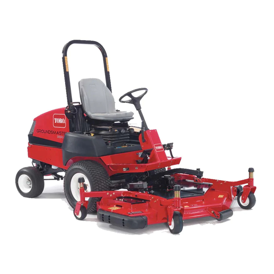
- Page 1 Form No. 3353–311 Rev C Groundsmaster 3505-D Groundsmaster Traction Unit Model No. 30826—Serial No. 250000001 and Up Operator’s Manual English (EN, GB)
-
Page 2: Table Of Contents
Checking the Cooling System ....The Toro General Commercial Products Warranty Checking the Hydraulic System .... -
Page 3: Introduction
Authorized Service and the proper use of the equipment. Dealer or Toro Customer Service and have the model and • Never allow children or people unfamiliar with these serial numbers of your product ready. The two numbers are instructions to use the mower. - Page 4 • Warning—fuel is highly flammable. Take the – Never mow across the face of the slope, unless the following precautions: machine is designed for that purpose. – Store fuel in containers specifically designed for this • Stay alert for holes in the terrain and other hidden purpose.
-
Page 5: Toro Mower Safety
The following list contains safety information specific to Maintenance and Storage Toro products or other safety information that you must • Keep all nuts, bolts, and screws tight to be sure the know that is not included in the CEN, ISO, or ANSI equipment is in safe working condition. -
Page 6: Sound Power Level
• Do not overspeed the engine by changing governor settings. To ensure safety and accuracy, have an • Do not operate on a side hill that is too steep. A rollover Authorized Toro Distributor check the maximum engine may occur before losing traction. speed with a tachometer. -
Page 7: Vibration Level
Vibration Level This unit does not exceed a vibration level of 0.5 m/s the posterior based on measurements of identical machines per ISO 2631 procedures. This unit does not exceed a vibration level of 2.5 m/s the hands based on measurements of identical machines per ISO 5349 procedures. - Page 8 107-7801 (for CE) 1. Tipping hazard—do not drive on slopes greater than 15 degrees. 43-8480 93-6681 1. Cutting/dismemberment hazard—stay away from moving parts. 104-0484 99-3444 1. Reel speed—fast 2. Reel speed—slow 104-1086 1. Height of cut...
- Page 9 106-6753 (for CE) 104-5181 (for CE) 1. Thrown object 2. Cutting/dismemberment hazard—keep bystanders hazard of hand or foot, 1. Warning—read the Operator’s Manual. a safe distance from the mower blade—stay away machine. from moving parts. 2. Tipping hazard—do not drive on slopes greater than 15 degrees and, if the roll bar is installed, wear the seat belt.
- Page 10 108-9006 1. Engage the power take off 3. Lower the cutting units. 6. Engine—stop 9. Fast (PTO). 4. Raise the cutting units. 7. Engine—run 10. Continuous variable setting 2. Disengage the power take 5. Move rear ward to lock the 8.
-
Page 11: Specifications
Specifications General Specifications Kubota three-cylinder, 4-cycle liquid-cooled diesel engine. 32 hp @ 2800 RPM, Engine governed to 3050 RPM. 68.5 cu. in. (1124 cc) displacement. Heavy-duty, 2-stage, remote mounted air cleaner. High water temperature shutdown switch. Radiator capacity is approximately 6 qt. of 50/50 mixture of ethylene glycol Cooling system anti-freeze. -
Page 12: Setup
Setup Note: Determine the left and right sides of the machine from the normal operating position. Loose Parts Note: Use this chart as a checklist to ensure that all parts necessary for assembly have been received. Without these parts, total setup cannot be completed. Some parts may have already been assembled at the factory. Description Qty. -
Page 13: Activating, Charging, And Connecting The Battery
Activating, Charging, and Warning Connecting the Battery Charging the battery produces gasses that can Warning explode. Never smoke near the battery and keep sparks and CALIFORNIA flames away from battery. Proposition 65 Warning 5. When the battery is charged, disconnect the charger Battery posts, terminals, and related accessories from the electrical outlet and battery posts. -
Page 14: Installing The Hood Latch (Ce)
If the clamp bolts are reversed, they may interfere with the hydraulic tubes when shifting the cutting units. 8. Coat both battery connections with Grafo 112X (skin over) grease, Toro Part No. 505-47, petroleum jelly, or light grease to prevent corrosion. Slide the rubber boot over the positive terminal. -
Page 15: Rear Ballast
2. Check to make sure that the clearance between each lift arm and stop bolt is 0.005–0.040 in. (0.13–1.02 mm) (Fig. 6). If the clearance is not in this range, adjust the stop bolts to attain clearance. Figure 8 1. Wear bar 2. -
Page 16: Before Operating
Filling the Fuel Tank (all temperatures) The engine runs on No. 2 diesel fuel. Toro Premium Engine oil is available from your distributor in either 15W–40 or 10W–30 viscosity. See the parts Fuel tank capacity is approximately 11 gallons. catalog for part numbers. -
Page 17: Checking The Cooling System
The cooling system is filled with a 50/50 solution of water and permanent ethylene glycol anti-freeze. Check the Alternate fluids: If the Toro fluid is not available, other coolant level at the beginning of each day before starting fluids may be used provided they meet all the following the engine. -
Page 18: Checking The Tire Pressure
This is vegetable–oil based biodegradable oil tested and result in personal injury or death. approved by Toro for this model. This fluid is not as Do not under-inflate the tires. resistant to to high temperatures as standard fluid, so install an oil cooler if required by the operator manual and follow recommended fluid change intervals with this fluid. -
Page 19: Operation
Operation Note: Determine the left and right sides of the machine from the normal operating position. Caution This machine produces sound levels in excess of 85 dBA at the operators ear and can cause hearing loss through extended periods of exposure. Wear hearing protection when operating this machine. -
Page 20: Starting And Stopping The Engine
Parking Brake Whenever the engine is shut off, the parking brake (Fig. 18) must be engaged to prevent accidental movement of the machine. To engage the parking brake, pull up on the lever. The engine will stop if the traction pedal is depressed with the parking brake engaged. -
Page 21: Bleeding The Fuel System
1. Be sure that the parking brake is set and the deck drive switch is in the Disengage position. 2. Remove your foot from the traction pedal and make sure that the pedal is in the neutral position. 3. Move the throttle lever to the 1/2 throttle position. 4. -
Page 22: Checking The Interlock System
Checking the Interlock System Caution If safety interlock switches are disconnected or damaged the machine could operate unexpectedly causing personal injury. • Do not tamper with the interlock switches. Figure 21 • Check the operation of the interlock switches 1. Bypass valve daily and replace any damaged switches before operating the machine. -
Page 23: Standard Control Module (Scm)
Standard Control Module (SCM) The Standard Control Module is a ”potted” electronic Output circuits are energized by an appropriate set of input device produced in a ”one size fits all” configuration. The conditions. The three outputs include PTO, ETR, and module uses solid state and mechanical components to START. - Page 24 – Indicates a circuit closed to ground. – LED ON O Indicates a circuit open to ground or de–energized – LED OFF + Indicates an energized circuit (clutch coil, solenoid, or start input) LED ON. ” ” A Blank indicates a circuit that is not involved with the logic. To troubleshoot, turn on the key without starting the engine.
-
Page 25: Operating Characteristics
Operating Characteristics If a person appears in or near the operating area, stop the machine, and do not start it again until the area is cleared. The machine is designed for one person. Never let anyone Danger else ride on the machine with you. This is extremely dangerous and could result in serious injury. - Page 26 After Mowing • Lower power requirement at lower heights and dense turf. At the completion of mowing operation, thoroughly wash High Lift Parallel Sail the machine with a garden hose without a nozzle so that excessive water pressure will not cause contamination and The blade generally performs better in the higher heights of damage to the seals and bearings.
- Page 27 Optional Equipment Configuration High Lift Parallel Sail Blade Standard Angle Sail DO NOT USE Mulching Baffle Roller Scraper Blade WITH MULCHING BAFFLE Has been shown to Grass Cutting: .75 improve dispersion Recommended in May work well in to 1.75 inch Height and after cut perfor- most applications light or sparse turf...
-
Page 28: Maintenance
Maintenance Note: Determine the left and right sides of the machine from the normal operating position. Recommended Maintenance Schedule Maintenance Service Maintenance Procedure Interval • Check the fan and alternator belt tension. After first 10 hours • Replace the hydraulic filter. •... -
Page 29: Daily Maintenance Checklist
Daily Maintenance Checklist Duplicate this page for routine use. For the week of: Mon. Tues. Wed. Thurs. Fri. Sat. Sun. Maintenance Check Item Check the safety interlock operation. Check brake operation. Check the engine oil level. Check the cooling system fluid level. Drain the water/fuel separator. -
Page 30: Greasing The Bearings And Bushings
• Cutting unit spindle shaft bearings (1 per cutting unit) (Fig. 33) • Rear roller bearings (2 per cutting unit) (Fig. 34) Note: The flush fittings on the rollers (Fig. 34) require a grease gun nozzle adapter. Order Toro Part No. 107–1998 from your Authorized Toro Distributor. Figure 24... - Page 31 Figure 28 Figure 25 Figure 29 Figure 26 Figure 30 Figure 27...
- Page 32 Figure 33 Figure 31 Figure 34 Figure 32 See note...
-
Page 33: Service Interval Chart
Service Interval Chart... -
Page 34: Removing The Hood
Removing the Hood force dirt through the filter into the intake tract. This cleaning process prevents debris from migrating into the intake when the primary filter is removed. The hood may be easily removed to ease maintenance procedures in the engine area of the machine. 1. -
Page 35: Servicing The Engine Oil And Filter
Servicing the Engine Oil and Servicing the Fuel System Filter Fuel Tank Change the oil and filter initially after the first 50 hours of Drain and clean the fuel tank every 2 years. Also, drain and operation; thereafter change the oil and filter every 150 clean the tank if the fuel system becomes contaminated or hours. -
Page 36: Bleeding Air From The Injectors
Replacing the Fuel Prefilter 4. Remove the clamp from the fuel filter and slide it onto the replacement filter. Push the fuel lines onto the Replace the fuel prefilter, located on the inside of the frame replacement fuel filter and secure them with the hose rail below the water separator, after every 400 operating clamps. -
Page 37: Servicing The Engine Belts
Alternator/Fan Belt 1. Turn the engine off and raise the hood. Clean the engine area thoroughly of all debris. 1. Open the hood. 2. Remove the access panel (Fig. 43). 2. Check the tension by depressing the belt midway between the alternator and crankshaft pulleys with 22 lb. -
Page 38: Adjusting The Throttle
Changing the Hydraulic Fluid Change the hydraulic fluid after every 400 operating hours, in normal conditions. If the fluid becomes contaminated, contact your local Toro distributor because the system must be flushed. Contaminated fluid looks milky or black when compared to clean oil. -
Page 39: Replacing The Hydraulic Filter
10 hours of operation, and thereafter every 200 hours of operation or yearly, whichever comes first. Use a genuine Toro oil filter for replacement. The hydraulic oil Adjusting the Traction Drive for must be changed every 400 hours of operation or yearly, Neutral whichever comes first. -
Page 40: Adjusting The Parking Brake
3. Loosen the locknut on the traction adjustment cam (Fig. 51). Figure 52 1. Parking brake lever 3. Set screw 2. Knob Figure 51 1. Traction adjustment cam 2. Locknut Caring for the Battery Warning The battery electrolyte level must be properly maintained and the top of the battery kept clean. -
Page 41: Storing The Battery
B. Clean the battery, terminals, and posts with a wire brush and baking soda solution. Warning C. Coat the cable terminals and battery posts with Grafo 112X skin-over grease (Toro Part No. 505-47) CALIFORNIA or petroleum jelly to prevent corrosion. Proposition 65 Warning D. -
Page 42: Electrical Schematic
Electrical Schematic... -
Page 43: Hydraulic Schematic
Hydraulic Schematic... -
Page 44: The Toro General Commercial Products Warranty
If for any reason you are dissatisfied with your Distributor’s service or have difficulty obtaining guarantee information, contact the Toro importer. If all other remedies fail, you may contact us at Toro Warranty Company.
Need help?
Do you have a question about the 30826 and is the answer not in the manual?
Questions and answers