H3C S3100-52P Installation Manual
Hide thumbs
Also See for S3100-52P:
- Operation manual (955 pages) ,
- Command manual (55 pages) ,
- Manual (40 pages)

Related Manuals for H3C S3100-52P


Summary of Contents for H3C S3100-52P
- Page 1 H3C S3100-52P Ethernet Switch Installation Manual Hangzhou H3C Technologies Co., Ltd. http://www.h3c.com Manual Version: T2-08048P-20070410-C-1.01...
- Page 2 Copyright © 2006-2007, Hangzhou H3C Technologies Co., Ltd. and its licensors All Rights Reserved No part of this manual may be reproduced or transmitted in any form or by any means without prior written consent of Hangzhou H3C Technologies Co., Ltd.
- Page 3 About This Manual Related Documentation In addition to this manual, each H3C S3100-52P Ethernet Switch documentation set includes the following: Manual Description It is used for assisting the users in H3C S3100-52P Ethernet Switch device configuration and typical Operation Manual applications.
- Page 4 Conventions The manual uses the following conventions: I. GUI conventions Convention Description Button names are inside angle brackets. For example, click < > <OK>. Window names, menu items, data table and field names are inside square brackets. For example, pop up the [New User] window.
-
Page 5: Table Of Contents
1.1 Introduction ........................1-1 1.2 S3100-52P Ethernet Switch....................1-1 1.2.1 Front Panel......................1-1 1.2.2 Rear Panel ......................1-5 1.3 System Features of the S3100-52P Ethernet Switch ............1-6 Chapter 2 Preparing for Installation .................... 2-1 2.1 Safety Precautions......................2-1 2.2 Installation Site........................2-1 2.2.1 Temperature/Humidity..................... - Page 6 Installation Manual H3C S3100-52P Ethernet Switch Table of Contents 5.2.2 Impact of File Attributes on Downloading and Booting ........... 5-2 5.2.3 Setting the Attribute of a File................... 5-3 5.3 Loading Software Locally....................5-5 5.3.1 Boot Menu ....................... 5-5 5.3.2 Loading Software from Console Port Using XModem ..........5-6 5.3.3 Loading Software from an Ethernet Port Using TFTP ..........
-
Page 7: Chapter 1 Product Overview
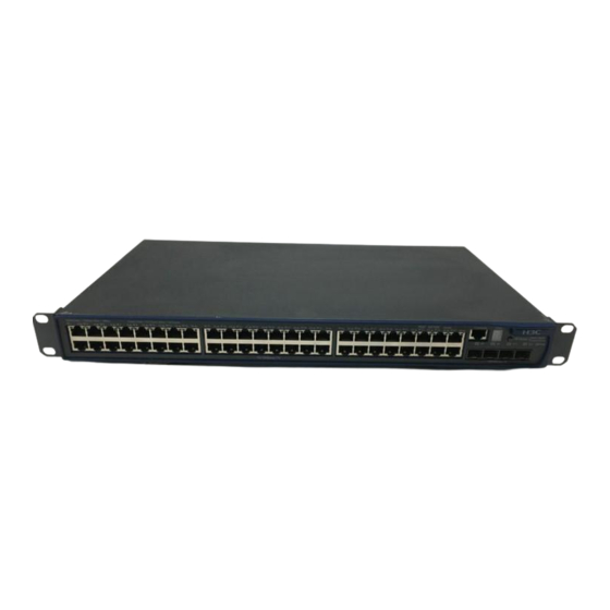
Chapter 1 Product Overview 1.1 Introduction H3C S3100-52P Ethernet Switch is wire speed layer 2 Ethernet switch. It is a intelligent NMS-manageable switch intended for the use in a network environment where high performance, dense port distribution, and ease of installation are required. - Page 8 Chapter 1 Product Overview II. LEDs The S3100-52P Ethernet switch provides one AC-input power LED, one port mode LED, one 7-segment digitron display, 48 x 10/100 Mbps Ethernet port status LEDs, and four SFP port status LEDs on its front panel. You can learn how it operates by reading the LEDs as shown in Table 1-2.
- Page 9 Installation Manual H3C S3100-52P Ethernet Switch Chapter 1 Product Overview Mark Color Indicates A 100 Mbps link is present. Green Data is being received/sent on the Flash port. A 10 Mbps link is present. Speed Yellow Data is being received/sent on the Flash port.
- Page 10 Button UNIT ID in the fabric; and for a Unit id released standalone unit, “1” III. Attributes of the 10Base-T/100Base-TX Ethernet ports Table 1-3 Attributes of the 10Base-T/100Base-TX Ethernet Ports on the S3100-52P Attribute Description Connector RJ-45 Number of ports...
-
Page 11: Rear Panel
The available SFP modules may change as time goes by. For the updated information about SFP modules, ask H3C marketing or technical support personnel. 1.2.2 Rear Panel The S3100-52P Ethernet switch has an AC power socket and a grounding screw on its rear panel, as shown in Figure 1-2. -
Page 12: System Features Of The S3100-52P Ethernet Switch
(2): Grounding screw Figure 1-2 Rear panel of the S3100-52P Following are the input voltage specifications of the S3100-52P Ethernet switch: Rated voltage: 100 to 240 VAC; 50 to 60 Hz Max. tolerance: 90 to 264 VAC; 50 to 60 Hz 1.3 System Features of the S3100-52P Ethernet Switch... -
Page 13: Chapter 2 Preparing For Installation
When replacing interface cards, wear ESD-protective gloves to avoid damaging the cards. 2.2 Installation Site The S3100-52P Ethernet switch must be used indoors. You can mount your switch in a rack or on a tabletop/workbench, but make sure: Adequate clearance is reserved at the air inlet/exhaust vents for ventilation. -
Page 14: Cleanness
Chapter 2 Preparing for Installation aging of insulation materials and can thus significantly lower reliability and service life of your switch. For the temperature/humidity requirement on the S3100-52P switch, refer to section 1.3 “System Features of the S3100-52P Ethernet Switch”. 2.2.2 Cleanness Dust is a hazard to the operating safety of your device. -
Page 15: Laser Safety
Caution: Staring into the laser beam produced by the fiber can hurt your eyes. 2.3 Installation Tools Flat-blade screwdriver Phillips screwdriver ESD-preventive wrist strap Caution: The installation tools are not provided with the S3100-52P Ethernet Switch. -
Page 16: Chapter 3 Installing The Switch
Use front mounting ears and a tray Use front mounting ears and guide rails Note: Guide rails purchased from H3C apply only to standard cabinets 1,000 mm (39.4 in) deep. Use other supports to substitute for guide rails in the case of other cabinet depths. - Page 17 Figure 3-1 Appearance of a standard front mounting ea Note: If you install a S3100-52P switch into a 19-inch standard cabinet, the configuration type of the front mounting ear is standard configuration. II. Use front mounting ears to install a switch...
- Page 18 Installation Manual H3C S3100-52P Ethernet Switch Chapter 3 Installing the Switch Place the switch horizontally in a proper position, and fix the other end of mounting ears to the front brackets with screws and captive nuts, as shown in Figure 3-3.
- Page 19 Slotted hole 2: Used to fix the guide rail to the front bracket Figure 3-4 Appearance of a guide ra Note: Guide rails purchased from H3C apply only to standard cabinets 1,000 mm (39.4 in) deep. Use other supports to substitute for guide rails in the case of other cabinet depths.
- Page 20 Installation Manual H3C S3100-52P Ethernet Switch Chapter 3 Installing the Switch Figure 3-5 Install guide rails Hold the two sides of the switch and slide it gently along the guide rails into the cabinet until it is located in a proper position, as shown in Figure 3-6. Ensure that the bottom side of the guide rails and the switch are in close contact.
-
Page 21: Mounting The Switch On A Tabletop/Workbench
Installation Manual H3C S3100-52P Ethernet Switch Chapter 3 Installing the Switch Guide Rear panel rail Figure 3-7 Effect diagram of front mounting ear and guide rail installatio Note: No guide rails are delivered with the device. Ensure a clearance of 1U (44.45 mm, namely, 1.75 inches) between devices for the purpose of heat dissipation. -
Page 22: Connecting The Ground Wire
Installation Manual H3C S3100-52P Ethernet Switch Chapter 3 Installing the Switch building was buried in the ground during the construction and wiring. Still, you must make sure of that. Figure 3-8 Power socket (recommended) II. Connecting the AC-input power cord Step 1: Connect one end of the chassis ground wire to the grounding screw on the rear of the chassis and the other end to the ground as near as possible. - Page 23 Installation Manual H3C S3100-52P Ethernet Switch Chapter 3 Installing the Switch Ground your switch as follows: When a grounding strip is available at the installation site, attach one end of the yellow/green ground wire of the switch to the grounding screw on the grounding strip and fasten the captive nut.
-
Page 24: Connecting The Switch To A Console Terminal
Installation Manual H3C S3100-52P Ethernet Switch Chapter 3 Installing the Switch (1): AC-input (2): Grounding screw (3): Power transformer (4): PE wire (5): AC-input (with 3-wire cable) (6): Ethernet switch Figure 3-11 Grounding through the AC PE wire 3.3 Connecting the Switch to a Console Terminal 3.3.1 Console Cable... -
Page 25: Connecting The Console Cable
Installation Manual H3C S3100-52P Ethernet Switch Chapter 3 Installing the Switch RJ-45 Signal Direction DB-9 → → 3.3.2 Connecting the Console Cable Follow these steps to connect a terminal device, a PC for example, to the switch: Step 1: Plug the DB-9 (female) connector of the Console cable to the serial port of the PC where the switch is to be configured. -
Page 26: Chapter 4 Starting Up The Switch At The Initial Boot
Installation Manual H3C S3100-52P Ethernet Switch Chapter 4 Starting up the Switch at the Initial Boot Chapter 4 Starting up the Switch at the Initial Boot 4.1 Setting up a Configuration Environment Set up a configuration environment as shown in Figure 4-1. - Page 27 Installation Manual H3C S3100-52P Ethernet Switch Chapter 4 Starting up the Switch at the Initial Boot Figure 4-2 Setting up a new connection Step 2: Enter the name of the new connection in the Name field and click <OK>. The dialog box, as shown in Figure 4-3 displays.
- Page 28 Installation Manual H3C S3100-52P Ethernet Switch Chapter 4 Starting up the Switch at the Initial Boot Parity check = none Stopbit = 1 Flow control = none Figure 4-4 Setting communications parameters Step 4: Click <OK>. The HyperTerminal dialogue box appears, as shown in Figure 4-5.
-
Page 29: Booting The Switch
The console cable is correctly connected. The console terminal (or PC) has been started and the related parameters have been set on it. 4.4.2 Powering up the Switch Starting..*********************************************************** H3C S3100-52P BOOTROM, Version 101 *********************************************************** Copyright(c) 2004-2007 Hangzhou H3C Technologies Co., Ltd. - Page 30 Installation Manual H3C S3100-52P Ethernet Switch Chapter 4 Starting up the Switch at the Initial Boot Creation date : Apr 10 2007, 21:27:49 CPU type : BCM4704 CPU Clock Speed : 200MHz BUS Clock Speed : 33MHz Memory Size : 64MB...
- Page 31 Press <0>. The system reboots with full startup mode and displays the following information: Starting..*********************************************************** H3C S3100-52P BOOTROM, Version 101 *********************************************************** Copyright(c) 2004-2007 Hangzhou H3C Technologies Co., Ltd. Creation date : Apr 10 2007, 21:27:49 CPU type : BCM4704 CPU Clock Speed : 200MHz...
- Page 32 If the specified host software does not exist, the switch will automatically choose an existing valid host software to boot. A wide range of command views are available for H3C Series Switches. For more information on configuration commands and command line interfaces, refer to H3C S3100-52P Ethernet Switch Operation Manual and H3C S3100-52P Ethernet Switch Command Manual.
-
Page 33: Chapter 5 Loading Boot Rom And Host Software
Installation Manual H3C S3100-52P Ethernet Switch Chapter 5 Loading Boot ROM and Host Software Chapter 5 Loading Boot ROM and Host Software Switch software loading through serial ports in the past is time consuming and cannot be operated remotely. To address these problems, TFTP and FTP are used to allow software and file downloading through Ethernet ports. -
Page 34: Impact Of File Attributes On Downloading And Booting
Installation Manual H3C S3100-52P Ethernet Switch Chapter 5 Loading Boot ROM and Host Software Attribute Usage Feature Identification Indicates a boot file with the Only one backup attribute. application file, When a device one configuration backup cannot boot with file, and one Web... -
Page 35: Setting The Attribute Of A File
Installation Manual H3C S3100-52P Ethernet Switch Chapter 5 Loading Boot ROM and Host Software Note: If a downloaded file has the same name as that of an existing file in the Flash, the new file will overwrite the original one, while having the same attributes. - Page 36 Installation Manual H3C S3100-52P Ethernet Switch Chapter 5 Loading Boot ROM and Host Software 3. set web files 0. return Enter your choice(0-3):1 II. Set the attributes of application, configuration, or Web files as needed. In this example, enter 1 to select “1. set application files”.
-
Page 37: Loading Software Locally
5.3.1 Boot Menu Starting..*********************************************************** H3C S3100-52P BOOTROM, Version 101 *********************************************************** Copyright(c) 2004-2007 Hangzhou H3C Technologies Co., Ltd. Creation date : Apr 10 2007, 21:27:49 CPU type : BCM4704 CPU Clock Speed : 200MHz... -
Page 38: Loading Software From Console Port Using Xmodem
Installation Manual H3C S3100-52P Ethernet Switch Chapter 5 Loading Boot ROM and Host Software Note: To access the Boot Menu, press <Ctrl+B> within one second after the information “Press Ctrl-B to enter Boot Menu...” appears; otherwise the system starts to decompress the program. - Page 39 Installation Manual H3C S3100-52P Ethernet Switch Chapter 5 Loading Boot ROM and Host Software II. Loading Boot ROM Follow these steps to download the Boot ROM program: Step 1: Enter <6> or <Ctrl + U> in the Boot Menu to access the Boot ROM loading...
- Page 40 Installation Manual H3C S3100-52P Ethernet Switch Chapter 5 Loading Boot ROM and Host Software Figure 5-1 Properties dialog box Figure 5-2 Console Port Configuration dialog box Step 5: Click <Disconnect> to disconnect the HyperTerminal from the switch and then click <Call> to re-establish the connection, thus validating the baud rate setting.
- Page 41 Installation Manual H3C S3100-52P Ethernet Switch Chapter 5 Loading Boot ROM and Host Software Figure 5-3 <Disconnect> and <Call> buttons Note: After changing terminal’s baud rate, you must disconnect and connect the terminal emulation program to validate the new configuration.
- Page 42 Installation Manual H3C S3100-52P Ethernet Switch Chapter 5 Loading Boot ROM and Host Software Figure 5-5 Sending File interface Step 9: After completing loading, the system displays the following information: Loading ...CCCCCCCCCC done! Note: You do not need to reset the HyperTerminal’s baud rate and can skip the last step if you have chosen 9600 bps.
-
Page 43: Loading Software From An Ethernet Port Using Tftp
Caution: TFTP Server program is not provided with the H3C Series Switches. Step 3: Run terminal emulation program on the PC that is connected to the Console port. Start the switch, access the Boot Menu, and then enter the download protocol menu. -
Page 44: Loading Software From An Ethernet Port Using Ftp
Installation Manual H3C S3100-52P Ethernet Switch Chapter 5 Loading Boot ROM and Host Software Step 5: Input the TFTP parameter values and press <Enter>. The system displays the following information: Are you sure to update your bootrom?Yes or No(Y/N) Step 6: Press <Y> to start file downloading and <N> to return to the program downloading menu. -
Page 45: Loading Software Remotely
Installation Manual H3C S3100-52P Ethernet Switch Chapter 5 Loading Boot ROM and Host Software 1. Set TFTP protocol parameter 2. Set FTP protocol parameter 3. Set XMODEM protocol parameter 0. Return to boot menu Enter your choice(0-3): Step 4: In the download protocol menu, press <2> to select FTP protocol to download Boot ROM and host software. -
Page 46: Loading Software Remotely Using Ftp
Installation Manual H3C S3100-52P Ethernet Switch Chapter 5 Loading Boot ROM and Host Software 5.4.1 Loading Software Remotely Using FTP Run FTP server on a local PC, provided you have configured username and password and have set the correct file directory. Suppose IP address of the PC is 10.10.110.1. -
Page 47: Loading Software Remotely Using Tftp
Installation Manual H3C S3100-52P Ethernet Switch Chapter 5 Loading Boot ROM and Host Software Note: Power disconnection must be prevented during the loading process. The configurations that you just make cannot survive a reboot. Make sure you have saved them before you have the system reboot. -
Page 48: Chapter 6 Maintenance And Troubleshooting
Installation Manual H3C S3100-52P Ethernet Switch Chapter 6 Maintenance and Troubleshooting Chapter 6 Maintenance and Troubleshooting 6.1 Dealing with Loading Failures If software loading fails, the system operates with the original version. To address the failure cause, take these steps: Check that the physical ports are correctly and securely connected. -
Page 49: Recovering The Boot Rom Password
Installation Manual H3C S3100-52P Ethernet Switch Chapter 6 Maintenance and Troubleshooting Select <7> and have the switch reboot. The user password is deleted at the reboot to allow you access the switch without password. 6.2.2 Recovering the Boot ROM Password Contact your sales agent for help. - Page 50 Installation Manual H3C S3100-52P Ethernet Switch Table of Contents Table of Contents Appendix A Lightning Protection of the Switch.................A-1 A.1 Installation of Lightning Arrester for AC Power (Socket Strip with Lightning Protection)..A-1 A.2 Installation of Lightning Arrester for Network Port.............A-2...
- Page 51 Installation Manual H3C S3100-52P Ethernet Switch Appendix A Lightning Protection of the Switch Appendix A Lightning Protection of the Switch A.1 Installation of Lightning Arrester for AC Power (Socket Strip with Lightning Protection) Caution: Lightning arrester will not be shipped with the switch. You should purchase it by yourself if needed.
- Page 52 Installation Manual H3C S3100-52P Ethernet Switch Appendix A Lightning Protection of the Switch Caution: Make sure that the arrester is well grounded before using the lightning arrester for power. After inserting AC power cord plug of switch into the socket of lightning arrester, if the green LED is on and the red LED does not alarm, it means that the lightning arrester of power is running and the function of lightning protection has taken effect.
- Page 53 Installation Manual H3C S3100-52P Ethernet Switch Appendix A Lightning Protection of the Switch Multimeter Tilted wire cutter II. Installation procedure Step 1: Tear the protection paper at one side of the double faced adhesive tape apart from the tape, and stick the tape on the surface of the arrester. Tear the protection paper at another side apart from the tape, and stick the arrester onto the chassis of the switch.
- Page 54 Installation Manual H3C S3100-52P Ethernet Switch Appendix A Lightning Protection of the Switch III. Installation precautions Fully consider the following items in the installation process, otherwise, the performance of the lightning arrester for network port will be affected: Lightning arrester for network port is installed in reverse direction. In practice, the “IN”...
Need help?
Do you have a question about the S3100-52P and is the answer not in the manual?
Questions and answers