Table of Contents
Advertisement
Quick Links
Advertisement
Table of Contents

Related Manuals for Crestron TPSBLOCK-10


Summary of Contents for Crestron TPSBLOCK-10
- Page 2 This document was prepared and written by the Technical Documentation department at: Crestron Electronics, Inc. 15 Volvo Drive Rockleigh, NJ 07647 1-888-CRESTRON All brand names, product names and trademarks are the property of their respective owners. ©2002 Crestron Electronics, Inc.
-
Page 3: Table Of Contents
Introduction...1 Industry Compliance...3 Installation...3 Custom Adapter Plates...5 Further Inquiries...6 Return and Warranty Policies ...7 Merchandise Returns / Repair Service...7 CRESTRON Limited Warranty...7 Installation Guide - DOC. 5979A 10-Position RJ45 Panel Mount Interface 10-Position RJ45 Panel Mount Interface: TPSBLOCK-10 • i... -
Page 5: 10-Position Rj45 Panel Mount Interface: Tpsblock-10
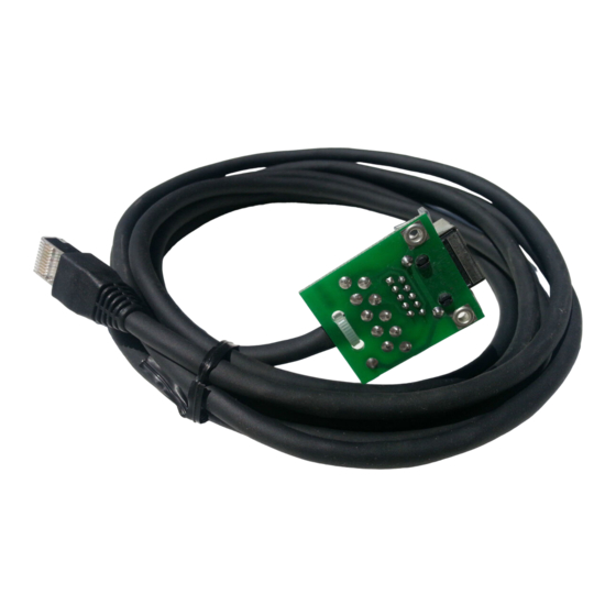
The touchpanel NET/VIDEO or RGB cable (supplied with the touchpanel) is connected to the female connector of the TPSBLOCK-10 and the TPSBLOCK-10 plug is connected to the Cresnet control system (via Crestron TPS interface module or optional TPS wall-mounted Installation Guide - DOC. 5979A 10-Position RJ45 Panel Mount Interface 10-Position RJ45 Panel Mount Interface: TPSBLOCK-10 •... - Page 6 NET/VIDEO and RGB applications. Pin 1 of the female connector is wired to pin 1 of the plug. Connector/Plug Pinouts DESIGNATION While facing the female connector of the TPSBLOCK-10, pin 1 is located at the upper-left of the connector. 2 • 10-Position RJ45 Panel Mount Interface: TPSBLOCK-10 INTERFACE MODULE AVAILABILITY DOC.
-
Page 7: Industry Compliance
Crestron TPSBLOCK-10 Peel-and-stick NET/VIDEO and RGB labels are supplied with the TPSBLOCK-10. If desired, a label may be affixed to the surface of the panel or desktop pop-up/tilt-up device. A matching AUDIO label is also supplied for use with non-Crestron 8-position RJ45 interface devices. - Page 8 (1.715 cm) 3. Refer to the diagram below. Using an electric drill and 0.136-inch (#29 or approximately 9/64-inch) drill bit, drill two TPSBLOCK-10 mounting holes. TPSBLOCK-10 Installation (2 of 3) - Mounting Hole Diagram 0.313 in (0.795 cm) 0.276 in (0.701 cm)
-
Page 9: Custom Adapter Plates
TPSBLOCK-10 Installation (3 of 3) - Secure TPSBLOCK-10 6. Connect the male RJ45 plug of the TPSBLOCK-10 cable to the NET/VIDEO or RGB port of the TPS interface module or TPS wall-mounted interface module. -
Page 10: Further Inquiries
If after reviewing this Installation Guide, you cannot locate specific information or have questions, please take advantage of Crestron's award winning customer service team by calling: • In the US and Canada, call Crestron’s corporate headquarters at 1-888-CRESTRON [1-888-273-7876] or 1-201-767-3400. • In Europe, call Crestron International at +32-15-50-99-50. -
Page 11: Return And Warranty Policies
CRESTRON shall not be liable to honor the terms of this warranty if the product has been used in any application other than that for which it was intended, or if it has been subjected to misuse, accidental damage, modification, or improper installation procedures. - Page 12 Crestron Electronics, Inc. Installation Guide - DOC. 5979A 15 Volvo Drive Rockleigh, NJ 07647 08.02 Tel: 888.CRESTRON Fax: 201.767.7576 Specifications subject to www.crestron.com change without notice.
Need help?
Do you have a question about the TPSBLOCK-10 and is the answer not in the manual?
Questions and answers