
Related Manuals for Texas Instruments TPS62203EVM-211


Summary of Contents for Texas Instruments TPS62203EVM-211
- Page 1 TPS62203EVM 211, TPS62200EVM 211 User’s Guide July 2002 PMP Portable Power SLVU069...
- Page 2 IMPORTANT NOTICE Texas Instruments Incorporated and its subsidiaries (TI) reserve the right to make corrections, modifications, enhancements, improvements, and other changes to its products and services at any time and to discontinue any product or service without notice. Customers should obtain the latest relevant information before placing orders and should verify that such information is current and complete.
- Page 3 EVM IMPORTANT NOTICE Texas Instruments (TI) provides the enclosed product(s) under the following conditions: This evaluation kit being sold by TI is intended for use for ENGINEERING DEVELOPMENT OR EVALUATION PURPOSES ONLY and is not considered by TI to be fit for commercial use. As such, the goods being provided may not be complete in terms of required design-, marketing-, and/or manufacturing-related protective considerations, including product safety measures typically found in the end product incorporating the goods.
- Page 4 EVM User’s Guide. When placing measurement probes near these devices during operation, please be aware that these devices may be very warm to the touch. Mailing Address: Texas Instruments Post Office Box 655303 Dallas, Texas 75265 Copyright 2002, Texas Instruments Incorporated...
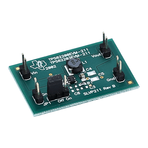
- Page 5 This users guide describes the characteristics, operation, and use of the TPS62200EVM-211 and TPS62203EVM-211 evaluation modules (EVM). These EVMs contain Texas Instruments high-efficiency buck converters that are configured to provide a regulated 3.3-V and 1.8-V output voltage and up to 300 mA of current. The users guide includes a schematic diagram, bill of materials (BOM), and test data.
-
Page 7: Table Of Contents
Contents Contents Introduction ..............Background . - Page 8 Contents Figures 2–1 Connection Diagram ............3–1 Top Assembly Layer .
-
Page 9: Introduction
Chapter 1 Introduction This chapter contains background information for the TPS62200EVM–211 and TPS62203EVM–211 evaluation modules. Topic Page Background ..........Performance Specification Summary . -
Page 10: Background
Background 1.1 Background This TPS6220XEVM uses a TPS6220X buck converter to step down 2.5-V or higher input voltages. This EVM operates over an input voltage range of 2.5 V to 6 V. The goal of the EVM is to demonstrate the small size of the TPS6220X power supply solution and provide flexibility in interchanging the supporting passive components. -
Page 11: Setup
Chapter 2 Setup and Test Results This chapter describes how to properly connect, setup, and use the TPS6220XEVM. Topic Page Input/Output Connections ........EVM Operation . -
Page 12: Input/Output Connect
Input/Output Connect 2.1 Input/Output Connect Figure 2–1 highlights the key connection points of the TPS6220XEVM. These connection points are described in the following paragraphs. 2.1.1 J1–Vin This is the positive connection to the input power supply. The leads to the input supply should be twisted and kept as short as possible. -
Page 13: Evm Operation
EVM Operation 2.2 EVM Operation As shown in Figure 2–1, an input power supply and a load must be connected to the appropriate EVM connectors in order for the EVM to operate. The absolute maximum input voltage is 7 V. The TPS6220X is designed to operate with a maximum input voltage of 6 V. -
Page 14: Board Layout
Chapter 3 Board Layout This chapter provides the TPS6220XEVM board layout and illustrations. Topic Page Layout ............Board Layout... -
Page 15: Layout
Layout 3.1 Layout Board layout is critical for all switch mode power supplies. Figures 3–1, 3–2, and 3–3 show the board layout for the SLVP211 PWB. The switching nodes with high frequency noise are isolated from the noise sensitive feedback cir- cuitry and careful attention has been given to the routing of high frequency cur- rent loops. -
Page 16: Bottom Layer Routing
Layout Figure 3–3. Bottom Layer Routing Board Layout... -
Page 17: Bill Of Materials And Schematics
Chapter 4 Bill of Materials and Schematics This chapter provides the TPS6220XEVM-211 bill of materials and schematics. Topic Page Bill of Materials ..........Schematics . -
Page 18: Bill Of Materials
Bill of Materials 4.1 Bill of Materials Table 6–1. Bill of Materials –001 –002 RefDes Description Size Part Number Capacitor, ceramic, 4.7 µF, 6.3 V, Murata GRM21BR60J475KA11 X5R, 20% Open Capacitor, ceramic, 33 pF, 50 V, Murata GRM1885C1H330CZ01 C0G, 5% Open Capacitor, ceramic, 10 µF, 6.3 V, C2012X5R0J106M... -
Page 19: Schematic
Schematics 4.2 Schematics Figure 4–1. TPS62200 Schematic 10 µH TPS62200DBV Vout = 1.8 V 475 kΩ 4.7 µF 33 pF 10 µF 182 kΩ 100 pF User Defined Figure 4–2. TPS62203 Schematic 10 µH TPS62203DBV Vout = 3.3 V 4.7 µF 10 µF User Defined Open... - Page 21 Authorized Distribution Brand: Website: Welcome to visit www.ameya360.com Contact Us: Address: 401 Building No.5, JiuGe Business Center, Lane 2301, Yishan Rd Minhang District, Shanghai , China Sales: Direct +86 (21) 6401-6692 Email amall@ameya360.com 800077892 Skype ameyasales1 ameyasales2 Customer Service: Email service@ameya360.com Partnership:...
Need help?
Do you have a question about the TPS62203EVM-211 and is the answer not in the manual?
Questions and answers