Advertisement
Quick Links
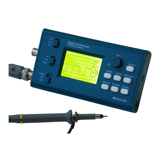
DSO 068 Oscilloscope DIY Kit
Assembly Guide
(
Step 1
Assembly the Main Board
1.
Complete the steps in "Get Ready" and understand soldering requirements.
2.
Install parts by the order of part list. Start from the back side of main board.
3.
Pay special attention to part polarity at soldering. Refer to photos to the right.
4.
For BOB boards and LCD soldering refer to photos at bottom for details.
5.
Perform power-up tests as suggested in the part list.
NOTE
: This photo is for PCB version H. PCB
version I is slightly different. Some parts have
been omitted or changed to SMD. Please see the
part list. Performance is not affected.
USB-Uart Conv.
Buzzer
Volt. Step-up Conv.
Reset
USB Socket
Batt. Charger
Power Switch
External
P.S. Conn.
Battery
Keypad
Conn.
Crystal
MCU
Main
LCD
MCU
Contrast
Back Side
Extention
Adj.
Ports
TIP: Do not install J4 if battery is to be mounted on back cover.Insert
the pins into programmer header to perform U4 and U5 programming.
BOB Boards Orientation
Pin 1 (square pad) indicated
by arrow
BOB Board Installation
BOBs and Jumpers
Keep JP1 open if BOB2
is installed. Otherwise
close it.
Keep JP2 open if BOB3
is installed. Otherwise
close it.
A.
Use the small acrylic
More at the reverse page
tool provided.
JYE Tech Ltd.
- www.jyetech.com -
Tools
1
Iron (20W)
PCB Version: H or I
)
2
Solder wire
Rev. 04
3
Multimeter
Identify
Polarity &
Orientation
TIP: Resistor values are easily
mis-read. Meter checking is
strongly suggested.
Neg. P.S.
JYE116
BOB4
Conv.
(
)
Pin 1 indicated by arrow
(
LED
Inductor
Diode
Electrolytic Cap.
Resistor
Ceramic Cap.
Cap. Trimmer
A/D Converter
Transistor
CBB Cap
TIP: C3 and R32
are not required.
Important! Unused leads under LCD must be cut flush to avoid short to LCD module!
LCD Installation
ASSY2 ASSY3
Cut leads short
under LCD
A.
B.
ASSY1
Lay PCB flat. Insert mount-
Identify the holes with labels
ing strips with longer pins
on LCD. They should go
into holes.
with the long strip.
B.
C.
Apply solder to one
Apply solder to the
pin.
corresponding pin on
main PCB.
Get Ready
4
Screw driver
1
Check part values & quantities against part list
5
Flush cutter
2
Meter and identify resistor values by ohm meter
6
Tweezers
Understand all part polarities and orientations
3
+
-
+
+
-
Diode
LED
Electrolytic cap.
JYE117
JYE118
JYE119
BOB3
BOB2
(
)
(
)
)
LCD Module
Test
Signal
Output
Slide Switch
Front Side
Labels
C.
D.
Put LCD onto strips as shown.
Solder pins at corners first. Do
the rest after flatness ensured.
D.
E.
Put BOB to place
Maintain BOB upright
and align pads.
and fix it by melting
the solder.
Soldering Skills and Requirements
1
Put leads through mounting from installation side of
PCB. Ensue they evenly touch PCB (picture below).
2
Solder at the other side of PCB. Solder should fully
fill and cover soldering pads.
Avoid bridges with
neighbering pads.
Cut unused leads
3
flush with cutter.
E
-
B
C
Note: Please install by the order given in the Part List below.
Transistor
Part List
Catagory
Seq.
1
PCB#: 109-06800-00H
Main PCB
JYE120
2
BOB1
BOB5
Resistor
(
)
(
)
3
4
5
Rotary Encoder
6
7
8
9
10
11
10K
12
1K
13
10M , 5
14
Jumper
15
1N4148 DO-35
Diode
16
100uH,
Inductor
17
20MHz
Crystal
18
USB socket,
Connector
19
Tact, 6 X 6 X 5mm
Switch
20
300pF, ceramic disk
Capacitor
21
3pF, ceramic disk
22
1pF, ceramic disk
23
120pF, ceramic disk
24
0.1uF , ceramic disk
25
15pF, ceramic disk
26
0.1uF/100V, CBB
27
5V, passive,
Buzzer
28
LED,
Diode
29
Connector
30
8550, TO-92 ( E-B-C)
Transistor
31
10uF,16V,
Electro.
Capacitor
32
100uF,16V, φ6X 7mm
33
DC005,
Connector
34
BOB
Board
35
36
37
38
Turn LCD and main board over.
Perform power-up test 1 as described on the reverse page.
Continue following assembly after the test.
Complete soldering following
same procedures as in C.
LCD
39
128X64 graphic, 12864-16
40
SIP, 2mm, 20X1
Pin
Strip
41
SIP, 2mm, 2X1
42
Slide switch SS-23D06
Switch
43
Rotary Enc., EC11, 10mm
Switch
44
Pin strip
DIP 2.54mm 5X2
45
Top(1), bottom(1), stand(1)
Enclosure
switch caps(3), dial cap(1)
46
7-key silicone button pad
Switch
47
BNC BNC-KY
Connector
F.
Finish the rest pins.
48
2-core header/wire, 10cm
Wire
49
2.3*8mm, self tapping
Screw
50
Shielding wire, 8cm
Wire
(Parts in
red
have been omitted for PCB version "I" )
Qty
Type/Spec
Designator/Location
1
510K
Ω,
5% 1/8W
,
2
R1, R27
200KΩ,
1% 1/8W
1
R3
,
2
R2, R4
2MΩ ,
1% 1/8W
,
1
R5
20KΩ,
1% 1/8W
,
300Ω ,
1% 1/8W
1
R6
,
1
R7
180Ω ,
1% 1/8W
,
3
R8, R12, R21
120 , 1%, 1/8W
Ω
3.3KΩ ,
1% 1/8W
,
2
R10, R22
3
R11, R31,
R33
470Ω,
1% 1/8W
,
Ω,
1
% 1/8W
,
3
R9, R20,R30
Ω ,
5
% 1/8W
5
R24,R25,R26,R28,R29
,
1
R40
Ω
%, 1/8W
Short with solder
1
JP9
,
2
D2,D3
3
L1,L4,L5
φ
2.5 X 6mm
1
Y1
,φ
2 X 6mm
1
MiNi-
B type
J1
1
SW12
C2,C23
2
1
C4
1
C6
3
C7, C13, C32
12
C9,C10,C11,C12,C14,
C15,C16,C18,
C20,
C24,
C25,C26
2
C21,C22
1
C1
1
BP1
9 X 5.5mm
φ
1
D1
φ
3mm
, red
1
J6
2pins, 2.54mm
2
Q1, Q2
1
φ X 5mm
4
C19
5
C17,C27,C28,C29,C30
1
J2
φ
2.1
mm core
1
BOB4
JYE116, step-up convertor
1
BOB5
JYE120, neg. P.S. convertor
1
BOB3 optional
JYE117, On/Off switch
(
)
1
BOB2(
optional
)
JYE118, battery charger
1
BOB1(
optional
)
JYE119,UART-USB conv.
1
LCD1
1
2
3
SW1,SW2,SW3
,
1
SW4
2
J4,J5 Do not install
,
,
(
1 set
Perform power-up
test 2 as described on
1
the reverse page after
2
,
all components have
1
been installed on
4
board.
1
)
Advertisement

Related Manuals for JYE Tech DSO 068


Summary of Contents for JYE Tech DSO 068
- Page 1 Soldering Skills and Requirements Tools Get Ready DSO 068 Oscilloscope DIY Kit Assembly Guide Put leads through mounting from installation side of Screw driver Iron (20W) Check part values & quantities against part list PCB Version: H or I PCB. Ensue they evenly touch PCB (picture below).
- Page 2 U3 has bad soldering Without BOB3 VS+ = V+ (due to JP2 closed) : voltage measurement With BOB3 VS+ depends on state of BOB3 (On or Off) : or has been damaged LCD defective JYE Tech Ltd. - www.jyetech.com -...
Need help?
Do you have a question about the DSO 068 and is the answer not in the manual?
Questions and answers