Table of Contents
Advertisement
Quick Links
Two-channel Oscilloscope DSO 094
Users Manual
Rev. 01
Applicable Model: 09401
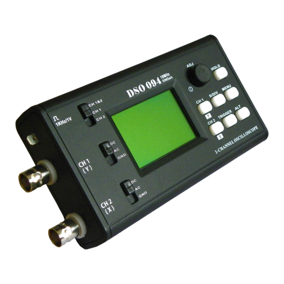
Panel & Connectors
Channel conf ig.
Test Signal
1Vpp / 1KHz
Ch 1 (Y) Input
Ch 1 Couple
Select
Ch 2 (X) Input
Ch 2 Couple
Select
Test Signal
1Vpp / 1KHz
Ch 1 (Y) Input
Ch 2 (X) Input
No connection
Modes & Menu
Y/T Mode
This is the most commonly used mode that
displays signal-to-time relationship.
Y/X Mode
This mode can be used to graph relationships
between two signals. In this mode Ch 1 becomes Y
and Ch 2 becomes X (see photo at right).
MENU
Menu is used to switch modes and perform special functions. Press [MENU] botton to enter menu
and press [HOLD] to execute selected item. Press [MENU] to exit.
Menu Function Summary
Item
Functions
DSO Y/T
Select Y/T mode
DSO Y/X
Select Y/X mode
SAVE WAVEFORM
Save Captured Waveform to EEPROM
RECALL WAVEFORM
SEND SCREEN
Send screen to PC as bitmap file
CHANGE REC. LEN
CHANGE TRIG POS
Change trig position (pre-trig buffer size)
CHANGE TRIG SEN
RESTORE DEFAULT
Restore settings to factory default
REBOOT
Reboot the oscilloscope (enter bootloader)
DN094-02v01/2012-05
For related documents please
www.jyetech.com
visit
Push: power ON
Hold: power OFF
Turn: adjustment
Tog gle RUN/HOLD
Ch 1 (Y) Sensitiviy & Position
Menu
Time base & Horizontal position
Alternative functions
Trigger Lev el, Slope, Source, & Mode
Ch 2 (X) Sensitiviy & Position
Trigger level in dicator
Ch 1
V. Pos
Ch 2
V. Pos
Trig Point
Dis playe d portion
USB Connector
Indicator
of capture buffer
Y/X Mode Screen
Y Pos.
X Pos.
Maximun allowed input voltages
are 50Vpk for 1X probe and 400Vpk
for 10X probe.
DO NOT ATTEMPT TO USE THE
DEVICE TO MEASURE LIVE
LINE VOLTAGE DIRECTLY!!!.
1. Powering ON/OFF the Device
Battery was disconnected for transportation reason. You need
connect it before powering the device up. Please follow the steps
below to connect battery:
Power On
Power Off
2. Setting Parameters
Frequently operated parameters are grouped into four catagories and governed by four buttons
respectively, as listed in the table below. When a parameter is selected the corresponding
Ch 1 sensitivity,
indicator is highlighted. Turning [ADJ] knob will change the parameter.
couple, & position
Catagory
Ch 2 sensitivity,
couple, & position
Ch 1
Vertical
Time ba se & H. Position
Trigger level,
Ch 2
slope, & source
Vertical
Trigger mode
Horizontal
Trigger
3. Special Functions
Y Pos.
The table below lists some frequently used special functions and related button actions.
X Pos.
Functions
Sampling
Toggle HOLD/RUN state
Rate
Bring up Function Menu
Y channel as
LCD backlight ON/OFF
trigge r source
Fast adjustment ON/OFF
Persistent display ON/OFF
IMPORTANT
Clear waveforms
Ch 1 0V level alignment
Ch 2 0V level alignment
4. About Rolling Display Mode
When Timebase is set to 0.1s/Div or slower DSO 094 enters
WARNING !
this mode traces shift (rolling) from right to left across screen to display slow signals.
5. Calibration of 10X probe
Please refer to the technical note "
Support/HowToCalibrate10xProbe.pdf) for details.
Basic Operations
First Time Powering UP
1 ) Unscrew the two screws at back cover. Remove back cover.
2 ) Battery was attached to the inner side of back cover. Insert its
connector to the header on PCB (marked as "BATT" at the side of
USB connector) as shown in the photo at right.
3 ) Put back cover back and screw it up.
- presssing [ADJ] knob
- holding down [ADJ] knob for about 2 - 3 seconds
Parameters
Selecting Button
Adjustment
Ø Sensitivity
[CH 1]
Turning
Ø Position
[ADJ]
Ø Couple
Ø Sensitivity
[CH 2]
Turning
Ø Position
[ADJ]
Ø Couple
Turning
Ø Time base
[S/DIV]
[ADJ]
Ø Position
Ø Level
[TRIGGER]
Turning
Ø Slope
[ADJ]
Ø Source
Ø Mode
Button Action
Explantions
Freezing waveforms for static veiwing
Pressing [HOLD]
Pressing [MENU]
Use menu to switch modes, save/recall waveforms, etc.
Holding [ALT]
Pressing [ALT] at
When vertical position (Ch 1 & Ch 2), horizontal position,
specific cussor
or trigger level is highlighted(selected) pressing [ALT] will
locations
turn on Fast Adjustment, which increases the adjustment
incremental to 5 (or 25 for H. position) from default value 1
Pressing [ALT] when
cursor is at Timebase
Holding [S/DIV]
Clearing the whole waveform buffer as well as display
Holding [CH 1]
Aligning 0V level of Ch 1 to its position indicator
Holding [CH 2]
Aligning 0V level of Ch 2 to its position indicator
How to Calibrate 10X Probe
Connect battery
Remarks
Couple is directly set by slide switch at
the left side of panel and not controlled
by [CH 1] button.
Couple is directly set by slide switch at
the left side of panel and not controlled
by [CH 1] button.
Rolling Display Mode
. In
" (www.jyetech.com/
Advertisement
Table of Contents

Related Manuals for JYE Tech DSO 094


Summary of Contents for JYE Tech DSO 094
- Page 1 4. About Rolling Display Mode RECALL WAVEFORM Recall saved waveforms SEND SCREEN Send screen to PC as bitmap file When Timebase is set to 0.1s/Div or slower DSO 094 enters Rolling Display Mode . In WARNING ! CHANGE REC. LEN Change record length (waveform buffer size) this mode traces shift (rolling) from right to left across screen to display slow signals.
- Page 2 Channel Configuration Advanced Operations DSO 094 can be set to display two channels or one channel only by the Channel Configuration Switch at top-left corner of panel. When it is set to one channel only Set up USB Connection the not-selected channel is not displayed. However, its signal is still captured.
Need help?
Do you have a question about the DSO 094 and is the answer not in the manual?
Questions and answers