Table of Contents
Advertisement
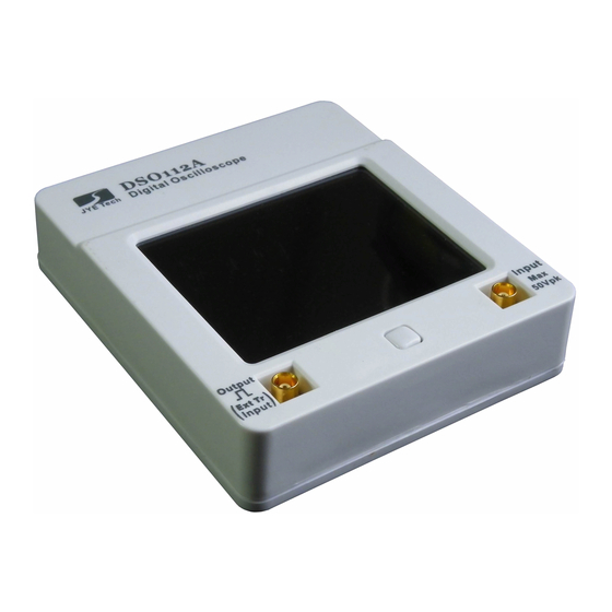
DSO112A Digital Oscilloscope
User Manual
Applicable Models: 11201A, 11202A, 11203A
Applicable Firmware Version: 113-11201-211 or later (for U1)
Before First Time Use ................................................................................................................... 3
Introduction ........................................................................................................................................... 3
Packing Contents ................................................................................................................................... 3
Switch on Battery .................................................................................................................................. 3
Charge Battery....................................................................................................................................... 4
Auto Power-off ...................................................................................................................................... 4
Panel and Connectors.................................................................................................................... 4
Main Working Screen ............................................................................................................................ 4
Connectors............................................................................................................................................. 5
Power Button ......................................................................................................................................... 6
Basic Operations ........................................................................................................................... 6
Power On/Off ........................................................................................................................................ 6
Probe a Signal........................................................................................................................................ 6
State Navigation .................................................................................................................................... 7
Booting Sequence .................................................................................................................................. 7
Adjust Sensitivity and Couple ............................................................................................................... 8
Adjust Timebase .................................................................................................................................... 8
Setup Trigger ......................................................................................................................................... 8
External Trigger................................................................................................................................... 10
Trigger Level ....................................................................................................................................... 10
Adjust Vertical Position ....................................................................................................................... 10
Adjust Horizontal Position................................................................................................................... 10
Hold State ............................................................................................................................................ 10
Select Record Length........................................................................................................................... 10
Test Signal Output ............................................................................................................................... 10
Advanced Operations.................................................................................................................. 11
VPos Alignment................................................................................................................................... 11
Save Waveform.................................................................................................................................... 11
Recall Waveform ................................................................................................................................. 11
Send Waveform Data ........................................................................................................................... 12
Restore Factory Default ....................................................................................................................... 15
Save/Recall Presets.............................................................................................................................. 15
Rename Presets.................................................................................................................................... 16
Enter Dashboard .................................................................................................................................. 16
Select Test Signal Frequency ............................................................................................................... 16
ΔT Cursors........................................................................................................................................... 17
ΔV Cursors .......................................................................................................................................... 17
Frequency Measurement...................................................................................................................... 17
Voltage Measurements......................................................................................................................... 17
Change Auto-off Time ......................................................................................................................... 17
Serial Interface (SI) ..................................................................................................................... 18
Introduction ......................................................................................................................................... 18
Output of Captured Data...................................................................................................................... 19
Output of Measurements...................................................................................................................... 20
Commands and Their Returns ............................................................................................................. 21
CSV Waveform File Format ................................................................................................................ 27
Use as Integration Module .......................................................................................................... 29
Connectors........................................................................................................................................... 29
Dimensions .......................................................................................................................................... 30
Maintenance ................................................................................................................................ 31
Charge Battery..................................................................................................................................... 31
JYE Tech
- 1 -
DN112-06v02
www.jyetech.com
Advertisement
Table of Contents

Related Manuals for JYE Tech DSO112A


Summary of Contents for JYE Tech DSO112A
-
Page 1: Table Of Contents
DN112-06v02 DSO112A Digital Oscilloscope User Manual Applicable Models: 11201A, 11202A, 11203A Applicable Firmware Version: 113-11201-211 or later (for U1) Before First Time Use ........................3 Introduction ............................3 Packing Contents ........................... 3 Switch on Battery ..........................3 Charge Battery............................4 Auto Power-off ............................ - Page 2 Appendix A: Coded Values of Oscilloscope Parameters............. 36 Values of Timebase ......................36 Values of Trigger Mode ...................... 36 Values of Trigger Slope....................... 36 Values of Couple......................... 37 Values of Vertical Sensitivity ....................37 Revision History ..........................37 JYE Tech - 2 - www.jyetech.com...
-
Page 3: Before First Time Use
DN112-06v02 Before First Time Use Introduction DSO112A is based on DSO112 with re-designed schematic and PCB. While keeping all functions and performance of its predecessor it exhibits significantly higher vertical sensitivity and ultra low background noises. As a small, light, accurate, and battery operated oscilloscope DSO112A is best for portable or field use. -
Page 4: Charge Battery
(photo below). The LED can be seen from outside of enclosure. After charge is completed the LED will turn off. To avoid waste of battery power DSO112A is with automatic Auto Power-off shut-down feature. When the unit is running on battery and there is no touch activity detected for a certain period of time the oscilloscope will shuts down itself. -
Page 5: Connectors
Trigger Position Indicator Indicating trigger position inside capture buffer which is represented by the green brackets. The following figure shows the functions and types of DSO112A Connectors connectors. Please note that the Test Signal Output connector is dual functional. It becomes external trigger input when external trigger is selected. -
Page 6: Power Button
Press the Power Button when battery or USB power has been connected. To Power Off DSO112A can be powered off in three ways: Ø In the main working screen touch the “Menu” button at top-left corner and select “Pwr Off” button. -
Page 7: State Navigation
DN112-06v02 State Navigation The following diagram shows the relationship of major working states. Tip: DSO112A uses resistive LCD panel. It will have better effects to operate with fingernail instead of finger belly as in operating a cellular phone. Booting Sequence When power button is pressed the oscilloscope is powered up. -
Page 8: Adjust Sensitivity And Couple
You need to adjust signal or oscilloscope parameters to make trigger happen in order to see waveform refresh. This mode is useful for capturing sparse signals. The temporary frozen effect makes sparse waveform stay on screen instead of just flash across. JYE Tech - 8 - www.jyetech.com... - Page 9 Vice versa, you will see more waveform before trigger. For DSO112A trigger position can be chosen to 1/8, 1/4, 1/2, 3/4, or 7/8 of capture buffer.
-
Page 10: External Trigger
When trigger mode is set to SING HOLD state will be entered automatically if valid trigger is detected. For DSO112A record length can be set to 512 or 1024 points. Select Record Length To change record length enter “Select Timebase” screen as stated in “Adjust Timebase”... -
Page 11: Advanced Operations
Recall Waveform Saved waveform can be recalled and displayed on screen without any change. To do this enter Menu and touch the button “Recall WF”. Recalled waveform is always displayed in HOLD state. JYE Tech - 11 - www.jyetech.com... -
Page 12: Send Waveform Data
Connect DSO112A oscilloscope to an USB port on PC. DSO112A contains a Uart-USB bridge CP2102. You need install driver on the PC for this chip if you are the first time using the PC for DSO112A. Please go to Silicone Lab website www.silabs.com to download the appropriate driver for your system and install it correctly. - Page 13 DN112-06v02 Select the port that is corresponding to DSO112A (you can identify it by going to Windows hardware manager and connecting/disconnecting the USB cable). Set parameters as shown in the figure above. Prepare data to be transferred. Capture the waveform you need and put DSO112A in HOLD state so that the captured data will not change.
- Page 14 Verify. Go to the folder where received file was stored and open it with Excel or a text reader. For the format of waveform data file please see detailed description in Section 5 later. JYE Tech - 14 - www.jyetech.com...
-
Page 15: Restore Factory Default
Please note that the previously saved settings in the selected location will be overwritten without warning. Touch “Load” button to recall the settings that have been previously saved in the selected location. The recalled settings will take JYE Tech - 15 - www.jyetech.com... -
Page 16: Rename Presets
1Hz, 10Hz, 100Hz, 1KHz, 10KHz, 100KHz, 1MHz, and 440Hz. To select different frequency enter Menu and touch the “Test Sig.” button. The Test Signal Frequency screen shows. Select the frequency wanted and touch “Done” button to finish. JYE Tech - 16 - www.jyetech.com... -
Page 17: Δt Cursors
Never. If there is no screen touch activity detected within the time period the oscilloscope will shut down itself. However, if external power supply (USB) is used the auto power-off timing is disabled. The unit will never shut down itself in this case. JYE Tech - 17 - www.jyetech.com... -
Page 18: Serial Interface (Si)
The USB connection is based on a CP2102 Uart-USB bridge inside DSO112A. You need install driver for this bridge on PC if it is the first time to connect to DSO112A. Please go to Silicone Lab website to download the appropriate driver for your system and install it correctly. -
Page 19: Output Of Captured Data
Standalone Mode where captured data are displayed on LCD panel as waveform. In situation where captured data are wanted DSO112A can be set USB Scope Mode. Under USB Scope mode waveform display on panel will be disabled. All captured data are output through the SI. -
Page 20: Output Of Measurements
100 * 4 * 20 = 8000 (uV) = 8mV If sensitivity is set 0.5V/Div the corresponding VR is 1000. The same measurement value (i.e. 100) represents 100 * 1000 * 20 = 2000000 (uV) = 2V JYE Tech - 20 - www.jyetech.com... -
Page 21: Commands And Their Returns
DN112-06v02 Commands and Their This section lists all available SI commands. These commands Returns can be sent to DSO112A through virtual COM port on USB or direct LVTTL connection at J11. Query Function: General query to determine oscilloscope type Format:... - Page 22 0xE9 Frame Size Reserved 0x00 Return: None Remarks: After received this command DSO112A will go back to standalone mode. Alternatively touch the “Exit” button on panel will Note: also make DSO112A exit USB Scope mode and back to standalone mode.
- Page 23 TrigModeMin TrigSlopeMax TrigSlopeMin TrigLvlMax TrigLvlMin TrigPosMax TrigPosMin TrigSrcMax TrigSrcMin Reserved RecLenMax RecLenMin Remarks: Get Parameters Function: Read the current parameters from DSO112A Format: Offset Field Name Size Value Sync character 0xFE Frame ID 0xC0 Frame Size Sub Command 0x21 Return:...
- Page 24 Field Name Size Value Sync character 0xFE Frame ID 0xC0 Frame Size Sub command 0x31 (for parameters) VSen VPos Reserved Timebase Reserved TrigMode TrigSlope TrigLvl TrigPos TrigSrc Reserved Measurements Record Length Reserved HPos Remarks: JYE Tech - 24 - www.jyetech.com...
- Page 25 DN112-06v02 Set Parameters Function: Set parameters to DSO112A. Newly set parameters take effect at next round capture. Format: Offset Field Name Size Value Sync character 0xFE Frame ID 0xC0 Frame Size Sub command 0x22 VSen VPos Reserved Timebase Reserved TrigMode...
- Page 26 Bit[7]: 1 – Recall the preset specified by Bit[6:0]. 0 – Load the preset specified by Bit[6:0]. Bit[6:0]: Index to the location where preset is to be recalled or saved. Valid range is 0 – 23. JYE Tech - 26 - www.jyetech.com...
-
Page 27: Csv Waveform File Format
Each field is an ASCII coded string or a null string. Header The CSV waveform file of DSO112A consists of a 16-line file header and multiple lines of data. The header contains device information and parameters for the samples that follow. The meanings of header lines and their fields are defined below. - Page 28 Line 10: Vertical sensitivity (Duplicate of line 5) Line 11: Reference. This is the value corresponding to 0V level. Line 12 – 16: Reserved. Sample Data Sample data start from line 17. Each line contains one sample. JYE Tech - 28 - www.jyetech.com...
-
Page 29: Use As Integration Module
DN112-06v02 Use as Integration Module DSO112A is also designed to be used as a module that can be integrated to user’s systems. Various alternative connectors are provided to make integration simple and easy. This photo shows the connectors which are useful for Connectors integration. -
Page 30: Dimensions
DN112-06v02 J11: This connector is for alternative UART. It is a LVTTL connection. Signal Pin# Name Output Input +3.3V Dimensions Unit: mm JYE Tech - 30 - www.jyetech.com... -
Page 31: Maintenance
DN112-06v02 Maintenance DSO112A contains a built-in smart Li-ion battery charger. By Charge Battery connecting the scope to a USB power supply charging will start and a red LED will light up indicating charge is undergoing. The LED can be seen from outside of case (see photo below). -
Page 32: Firmware Upgrade
Sometimes you might need to upgrade firmware to acquire new features or higher performance. There are two ways to change the firmware for DSO112A. One is by the pre-installed bootloader. The other is by a programmer. Upgrade Firmware by Bootloader Connect DSO112A oscilloscope to an USB port on PC. - Page 33 “Maximum connection count” to 100. This will make connection easier. Change settings on tab “Com Port”. Com port number should be chosen to the one corresponding to DSO112A. Communication format must be set to 9600 bps, 8N1, no parity and flow control. Then click OK button.
- Page 34 There are many such programmer available on the market (for example, sku# 07302 from JYE Tech). It is important to make sure that the connection between programmer and J3 on DSO112A is correct. The table below describes the signal names on J3. J3 Pin-out Description...
-
Page 35: Troubleshooting
Auto shutdown when powered by battery Display Screen 2.4” Color TFT LCD with Touch Panel Power Supply Power Supply Type 3.7V/1200mAh Li-ion Battery or USB Power Supply Current < 300mA @ 3.7V Physical Dimension 80mm X 70mm X 18mm JYE Tech - 35 - www.jyetech.com... -
Page 36: Appendix A: Coded Values Of Oscilloscope Parameters
20us/div 0x1A 0x1B 10us/div 0x1C 5us/div 2us/div 0x1E 1us/div 0x1E 2) Values of Trigger Mode Setting Values Auto 0x00 Normal 0x01 Single 0x02 3) Values of Trigger Slope Setting Values Falling 0x00 0x01 Rising JYE Tech - 36 - www.jyetech.com... -
Page 37: Values Of Couple
3) Modified description for captured data output of Serial Interface to reflect changes in firmware version 113-11201-211. 4) Modified the values of vertical sensitivity and timebase. These value change was made in 113-11201-211 for future compatibility. JYE Tech - 37 - www.jyetech.com...
Need help?
Do you have a question about the DSO112A and is the answer not in the manual?
Questions and answers