Advertisement
Quick Links
DSO138mini Oscilloscope DIY Kit
User Manual
Tools you need
Screw driver
1
Iron (20W)
4
Flush cutter
2
Solder wire
5
Multimeter
6
Tweezers
3
Notes
1
Instructions for optional parts (including
charger
) are not given in this manual. If you have purchased these parts please
refer to their own manuals available at
2
Please visit
www.jyetech.com
for other documents about schematics,
troubleshooting, firmware upgrade, mechanical, waveform upload, etc.
3
Items marked with [H] are for analog board ver. H. Items marked with [J] are for
analog board ver. J.
Step 2
Assembly Analog Board (follow the order as numbered)
1. Resistors
Note:
Always meter resistor
values before soldering
because color bands are
easy to mis-read.
Resistors are all 1/8W.
R5
:
20KΩ
R1, R13
:
100KΩ
R6, R14, R17
:
300Ω
R2
1.8MΩ
:
R7, R11
:
180Ω
R3, R15
:
200KΩ
R8, R12
:
120Ω
R4
:
2MΩ
R9, R10, R16
:
1.1KΩ
2. Diode
Cathode
Zener, 2.0V
D1
:
3. HF-Chokes
L1,L2
:
100 H
μ
JYETech Ltd.
- www.jyetech.com -
(Model: 13805K)
Applicable PCB: Main:
109-13800-00I
Analog: 109-13801-00[H, J]
Rev. 05
Applicable firmware: 113-13810-110 or later
Before you start
1
Check values & quantities against parts listed
2
Understand all part polarities and orientations
3
Prepare a USB cable with USB-micro connector
BNC probe, enclosure,
and
battery
www.jyetech.com
.
4. LED
Solder positive pole
D2
(the longer lead) to
the square pad
5. Capacitor trimmers
C4
:
C6
5 - 30pF (green)[H]
:
2 - 6pF (blue)[J]
6. Ceramic Capacitors
C1
C2
C3
C5
C7
Step 1
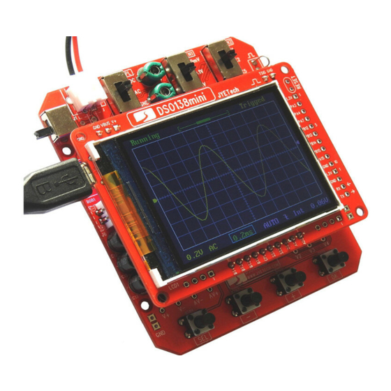
Test and Assembly Main Board
1. Check the main board
Before mounting any parts to the main board
1
Use an USB cable with USB-Micro plug to power
the main board through J7.
2
You should see the scope boots up to a screen
similar to the photo below. D1 (LED) should
blink three times during the booting.
1
Apply power
7. Pin header
LED, blue,
:
8. Electrolytic capacitors
dia. 3mm
5 - 30pF (green)
Solder positive pole
(the longer lead) to
the square pad
9. Slide switches
:
0.1 F
μ
:
220pF
3pF
:
1pF [ver. H only]
:
[ H ]
:
120pF [H]
500pF [J]
SW1, SW2, SW3
:
2P3T
Tech Support: www.jyetech.com/forum
2. Pin-headers (female)
2
Check
display
Atte ntion
Do not solder any parts to the board if
you find problem. Otherwise warranty
will be voided. Report to your vender
or JYE Tech for any problem found.
10. Pin-headers (male)
J1, J6
:
2 Pin, 2.54mm,
rightangled
Note:
Do not install J1 if BNC
11. Test signal ring
connector is to be used.
12. Tact Switches
C10, C11,
:
100 μ /1 6 V
F
C12, C13,
C14
13. Jumpers
[ J ]
SW4
DPDT
:
J4
:
1 X 10 pin
:
J8
1 X 2 pin
J9
:
1 X 3 pin
J5
:
1 X 10 pin
J2
:
1 X 3 pin
J3
:
1 X 2 pin
1 ) Make a small ring with a
lead cut-off.
2 ) Solder the ring to the two
holes of J4 (as shown in
the photo).
:
6 X 6 X 9mm
BTN1, BTN2,
BTN3, BTN4
Short JP2 and JP3with
solder (see photo at left).
Keep JP4, JP5, JP6 (on
the bottom side) open.
JP1 has been pre-shorted.
Page 1
Advertisement

Subscribe to Our Youtube Channel
Related Manuals for JYE Tech DSO138mini


Summary of Contents for JYE Tech DSO138mini
- Page 1 Report to your vender Apply power or JYE Tech for any problem found. Items marked with [H] are for analog board ver. H. Items marked with [J] are for analog board ver. J.
- Page 2 Calibrating C4 & C6 14. Hook Probes Finished look Insert hook probe to J1. Connect the red hook to the test signal Leave black hook Connect red hook to terminal J4 and leave the black hook un-connected. un-connected test signal output Set [SEN1] switch to 0.1V and [SEN2] switch to X5.
Need help?
Do you have a question about the DSO138mini and is the answer not in the manual?
Questions and answers