Advertisement
Quick Links
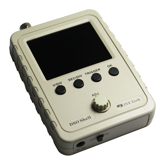
Shell
DSO
DIY Kit
User Manual
Applicable models: 15001K, 15002K
Applicable firmware version: 113-15001-110 or later
Before you start
1
Check kit contents and part quantities/values by the photo at right and part list in page2
and page 3. Report missing or wrong parts to your vendor.
2
Resistor values are easy to mis-read. It is strongly suggested to check their values
by ohm-meter before soldering them to board.
3
Make sure you understand the polarities and orientations of all parts.
Important !!!
If your have purchased 15002K kit (SMD not pre-soldered) you must install all
SMD parts before mounting the through-hole parts. Please refer to the instructions
below for SMD part installation. Otherwise, proceed to page2 to start through-hole
part assembly.
SMD parts are only installed to the analog board (PCB PN# 109-15001-xxx).
How to Solder SMD Parts
1. Before soldering check components against the
part list to make sure you have correct parts.
2. Identify IC orientation and diode polarity (see photos).
3. Do not put iron on one pad for too long time. Otherwise,
traces may peel off and get damaged.
SMD Part Lis
(For PCB 109-15001-00F)
Qty
Descriptions
Loc/Ref
1
TL084, SO14
U1
74HC4053, SO16
U2
1
74HC4051, SO16
1
U3
U4
1
78L05, SOT89
1
U5
ICL7660, SO8
U6
1
79L05, SOT89
R19, R20
2
1K,1%, 0805
R17, R18
2
10K,1%, 0805
2
C3, C5
Cap trimmer, 30pF
8
0.1uF, 50V, 0805
C9, C12, C13, C14,
C15, C16, C17, C18
JYE Tech Ltd.
- www.jyetech.com -
See page 2 for
tools needed
Rev. 08
Solder ICs
Pin1
Apply solder to a corner
Identify IC orientation
pad
TL 084 C
Solder two-terminal parts
PIN 1
Place IC in front of
you so that its marking
read from left to right.
The first pin at lower-
left corner is pin 1.
Apply solder to one pad
Solder IC to the pad. Make
Solder the pin at the opposite
sure pins are aligned to pads
corner so as chip is fixed
Solder the other pad
Solder part to the pad
Solder all the rest pins one
by one
Note:
Photos here are for
illustration only.
They may not match
the real board.
Page 1
Advertisement

Related Manuals for JYE Tech DSO Shell 150


Summary of Contents for JYE Tech DSO Shell 150
- Page 1 C9, C12, C13, C14, The first pin at lower- C15, C16, C17, C18 left corner is pin 1. Solder the other pad Solder part to the pad Apply solder to one pad JYE Tech Ltd. - www.jyetech.com - Page 1...
- Page 2 300Ω Do not solder any parts to the board if you find problem. Otherwise warranty will be voided. R8, R16 150Ω Report the problem to vender or JYE Tech. Solder positive pole 510KΩ C8, C10, 100 μ /1 6V 5. Pin-header (male) 91Ω...
- Page 3 Firmly press the frame in Screw up at the back Attach the front frame Knob cap Front frame Important ! Make sure PCB evenly Screws PA2.3x8 touch the front plate (4 positions) while doing C. Page 3 JYE Tech Ltd. - www.jyetech.com -...
- Page 4 Max input voltage 50Vpk (1X probe) Power supply 9V DC (8 – 10V) Input impedance 1M ohm/20pF Current consumption ~120mA @ 9V JYE Tech Ltd. Resolution 12 bits Dimension 105 x 75 x 22mm Record length 1024 points Weight 100 gram (without probe and PS) www.jyetech.com...
Need help?
Do you have a question about the DSO Shell 150 and is the answer not in the manual?
Questions and answers