
Related Manuals for Philips Allegiant LTC 8500 Series


Summary of Contents for Philips Allegiant LTC 8500 Series
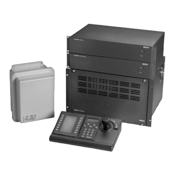
- Page 1 ® Allegiant Microprocessor-Based Video Switcher/Control Systems LTC 8500 Series LTC 8600 Series LTC 8800 Series Philips Communication & Security Systems...
- Page 3 This Instruction Book refers to “TC- prefix” model designations. Use this cross-reference to find the new corresponding “LTC-prefix” model numbers. A revised instruction book will be printed at a later date. ® LTC 8900 Allegiant Microprocessor-Based Video Switcher/Control Systems LTC 8901/00 ---- Equipment Rack, for LTC 8901 Bay LTC 8905/90...
- Page 4 ® Allegiant System Accessories LTC 8550/00 TC8550A Keyboard, Joystick Control LTC 8551/00 TC8551A Keyboard, Push Button Control LTC 8552/00 TC8553-232 Keyboard, Variable Speed, RS-232, Joystick Control LTC 8553/00 TC8553 Keyboard, Variable Speed, Joystick Control LTC 8554/00 TC8554 Keyboard, Compact, Push Button Control LTC 8555/00 TC8555 Keyboard, Compact, Variable Speed Joystick Control...
- Page 5 16. Servicing - Do not attempt to service this unit yourself as opening or IMPORTANT SAFEGUARDS removing covers may expose you to dangerous voltage or other hazards. Refer all servicing to qualified service personnel. Read Instructions - All the safety and operating instructions should 17.
- Page 6 Power SAFETY PRECAUTIONS Power Disconnect. Units with or without ON-OFF switches have power supplied to CAUTION the unit whenever the power cord is RISK OF ELECTRIC SHOCK. DO NOT OPEN! inserted into the power source; however, the unit is operational only when the ON- CAUTION: TO REDUCE THE RISK OF ELECTRICAL OFF switch is in the ON position.
-
Page 7: Table Of Contents
TABLE OF CONTENTS Keyboard Controls..............35 UNPACKING ............6 Switcher Control Keys ............36 SERVICE ..............6 Function Keys ................ 36 DESCRIPTION ............6 Telemetry Controls ..............36 ALLEGIANT FEATURE SUMMARY TABLE ..7 VIDEO MONITOR DISPLAY......... 37 MAJOR SYSTEM COMPONENTS ......9 Time/Date ................ -
Page 8: Unpacking
If the unit ever needs repair service, the customer state (as it leaves the factory) or can be customized should contact the nearest Philips Communication & with our optional TC8850 Graphical User Interface Security Systems Service Center for authorization to Software package or our optional TC8x59 Master return and shipping instructions. -
Page 9: Allegiant Feature Summary Table
The addition of the optional TC8850 Graphical User ALLEGIANT FEATURE Interface Software package or the optional TC8x59 Master Control Software package enables the user to SUMMARY TABLE customize the system's configuration using a menu driven program run on an IBM compatible personal The Allegiant system is available in two operating computer. - Page 10 In addition, all systems provide the capability to 4. User log-on to keyboard or console port. control on-site receiver/driver units including the 5. Console broadcast message. AutoDome™ series of integral pan/tilt/zoom/camera dome series. 6. Console transfer of system tables. All systems contain a logging printer output port to 7.
-
Page 11: Major System Components
MAJOR SYSTEM COMPONENTS TC8x01 Main CPU Bay System Capabilities A modular equipment bay which contains the These tables indicate the maximum number of video system’s microprocessor module (TC8511C or input and output modules that each equipment bay TC8x10A), the power supply module (TC8x05), and may hold, as well as the number of individual inputs several video input and video output modules (see or outputs supported by each of these modules. -
Page 12: Supplementary System Components
SUPPLEMENTARY SYSTEM COMPONENTS The Allegiant accessory products provide many Rack mounting kit designed to provide vertical, optional features to the base system. A brief horizontal or 30° inclined mounting for TC8550A, description of accessory products is provided below. TC8551A, or TC8553 keyboards. Complete specification information can be found in their respective product data sheets. -
Page 13: Tc700 Series Autodomes
Decodes data transmitted from TC8568 unit for TC8770I Interconnect Panel camera site control of Pan/Tilt, Zoom Lens, pre- Accessory for the TC8770 Switcher Follower which positions, and auxiliaries. Unit contains integral local provides convenient screw terminal interface for test feature, auto-pan or random scanning, and is external connections. -
Page 14: Tc8780 Series Data Converter Units
TC8135 Series controller/followers into standard manufacturer code formats. Contact your Philips RS-232, and converts RS-232 back to biphase code. local manufacturer’s representative for additional This provides the capability of transmitting the information. biphase control code over conventional RS-232... -
Page 15: Tc8779Se Service Extender Card
Software program, interface cable, and Users TC8779SE Service Extender Card Manual for custom programming of Allegiant system. Service extender card used for troubleshooting A special version, the TC8059, includes multiple TC8600 and TC8800 CPU and video output modules disks for programming TC8500 Series, TC8600 and all TC8700 modules. - Page 16 Up To 64 Video Inputs Maximum Additional System Cameras TC8511A TC8521VIM TC8505PS Module TC8532VOM 8 x 8 CH 4 x 2 CH Power Input Cards Output Cards Supply Module TC8501B SERIES MAIN CPU BAY 3 m (10 ft) Interconnect Cable Supplied With Keyboard Up to 8 Monitor Outputs Video Coax Monitor 7...
- Page 17 Up To 128 Video Inputs Maximum Additional System Cameras TC8610A TC8621 TC8834 Module TC8605 8 x 16 CH 4 x 4 CH Power Input Cards Output Cards Supply Module TC8601 Series Main CPU Bay 3 m (10 ft) Interconnect Cable Supplied With Keyboard Up to 16 Monitor Outputs Video Coax...
- Page 18 Up To 256 Video Inputs Maximum Additional System Cameras TC8834 TC8821 TC8810A 8 x 4 CH 8 x 32 CH Output Cards Input Cards Module TC8805 Power Supply Module TC8801 Series Main CPU Bay Up to 32 Monitor Outputs 3 m (10 ft) Interconnect Cable Supplied With Keyboard Multiple Video Coax Monitor 1...
- Page 19 Up To 256 Video Coax Ribbon Jumper Cables Inputs Maximum (Supplied) TC8816A TC8821 TC8834 TC8810A TC8821 TC8834 Data 8 x 32 CH 8 x 32 CH 8 x 4 CH 8 x 4 CH Receiver Input Cards Output Cards Module Input Cards Output Cards Module...
- Page 20 64 Separate Alarm Inputs Typical AutoDome™ Video Camera Twisted-Pair Coax Contact Closure Typical or Active Low Logic Level TC8540C Alarm Interface Unit Video Coax 2 m (6 ft) Interconnect Cable Supplied With Up to 1.5 km (5000 ft) Pan/ TC8561A TC8540C Providing Data Using 18 g Shielded Tilt...
- Page 21 Up to 64 Alarm Inputs to Each TC8540C Unit Typical 8 Pairs AutoDome™ of Relay Video Camera Outputs Coax Contact Closure Up to 1.5 km (5000 ft) or Logic Level Using 18 g Shielded Inputs Twisted Pair Cable (Belden 8760 or Equiv.) TC8540C Alarm TC8540C Alarm Twisted...
-
Page 22: Installation Procedure
INSTALLATION PROCEDURE CAUTION: Do Not Apply power to equipment until instructed to do so. Main CPU Bay Installation Video Input Modules Before discarding the shipping cartons, verify that For TC8600 and TC8800 systems, termination the various pieces of equipment have no evidence of switches on the Video Input Modules (VIM) must be carrier damage. -
Page 23: Video Output Modules
Video Output Modules The next set of slots can contain up to 4 (8 on the TC8800) Video Output Modules (TC8834 TC8532VOM). If counting from left to right, these are slots 9 to 12 for the TC8500 and TC8600, and 9 to 16 for the TC8800. -
Page 24: Tc8600 And Tc8800 Video Inputs
TC8600 and TC8800 Video Inputs Termination Practices The TC8601 and TC8801 main bays have only 96 Video from every camera should be "terminated" direct BNC connectors available for video input. with a 75 ohm resistance. Each video line should be Cameras above 96 require the use of the TC8808 terminated exactly once. -
Page 25: Keyboard Hookup
If a TC8802 monitor expansion bay is supplied, each Keyboard Hookup camera that is connected to the TC8801 main CPU Connect a maximum of 8 system keyboards to any bay must also be connected to the same numbered of the 8 keyboard ports (modular phone type jacks) input on the monitor expansion bay. - Page 26 connected to one of the data outputs of the TC8569- Satellite Site “Trunk Line” 2 Series unit. Monitor Outputs At each of the remote satellite sites, a desired Satellite Site Programming Requirements number of monitor outputs from the switcher must be The optional TC8850 Graphical User Interface assigned as Trunk lines.
- Page 27 setup), the monitor outputs being used as Trunk lines actual cameras need to be entered. For example, all are automatically disabled from local control as soon 12 cameras associated with a 12-position TC8112B as the first commands are received from the main switcher do not need to be entered if only 5 cameras site.
-
Page 28: Feature Selection
Installations having cameras powered from an AC Feature Selection phase different than that of the Allegiant system may Certain user-selectable features provide utilize the built in EXTERNAL SYNC input or vertical enhanced Allegiant system operation capabilities. PHASE ADJUST. Any desired changes can be made now or delayed NOTE: ALL CAMERAS SHOULD BE PHASED until specific system requirements become more PROPERLY WITH EACH OTHER BEFORE THE... - Page 29 S932A17AE TC8501 Series Back Panel Artwork TC8600 Series Back Panel Artwork...
- Page 30 S932A20AE TC8808 Series Panel Artwork...
- Page 31 TC8801 Series Back Panel Artwork S9508035AE TC8802 Series Back Panel Artwork...
-
Page 32: Optional Accessories
OPTIONAL ACCESSORIES Logging Printer Option Installation IBM or IBM Compatible Computer Interface Installation Note: Although the exact installation procedure for each printer varies, the following steps are generally NOTE: Although the exact installation procedure for required. Be sure to save the printer reference each computer varies, the following steps are manual for procedures not covered. -
Page 33: System Keyboards - Tc8550A, Tc8551A, Tc8553 Series
SYSTEM KEYBOARDS - TC8550A, TC8551A, TC8553 Series The various system keyboard displays and functions for the TC8550A, TC8551A, and TC8553 Series are described herein. Refer to the applicable keyboard diagrams as needed. Monitor Number Display Lens Control Mode Displays Rocker Switches Camera Number Display (LEDs) Pan/Tilt Joystick... -
Page 34: Keyboard Controls
data entry. Holding this key when using the ON or ON LINE Display OFF functions will cause those functions to repeat Directly above the camera display is the ON LINE until the key is released. display. The LINE part of the display indicates the keyboard is electrically connected to the Allegiant Switcher Control Keys system. -
Page 35: Telemetry Controls
OFF / OUT - OFF deselects any receiver/driver Telemetry Controls auxiliary functions currently in the 'on' state. The Telemetry controls activate the camera movements. OUT key deletes the current sequence step when These keys will transmit commands programming. This is actually a single key with two receiver/drivers at remote camera sites as long as separate functions. -
Page 36: System Keyboards - Tc8554, Tc8555
SYSTEM KEYBOARDS - TC8554, TC8555 The various system keyboard displays and functions for the TC8554 and TC8555 are described herein. Refer to the applicable keyboard diagrams as needed. S9510001AE TC8554 Keyboard S9510002AE TC8555 Keyboard... -
Page 37: Keyboard Displays
Keyboard Displays Mode Displays The Mode displays are various indicators that light Monitor Display up within certain keys to show the keyboard status. The monitor display is a three-digit seven-segment The keyboard will stay in a selected mode until all display that serves two purposes. -
Page 38: Switcher Control Keys
SET - Press SET to record a preset scene at a Switcher Control Keys remote camera site. The switcher control keys control the Allegiant SHOT - Press SHOT to call up a preset scene at a switching and programming functions. remote camera site. -
Page 39: Video Monitor Display
VIDEO MONITOR DISPLAY Although the video display is not part of the TC8550 power. The display is updated once per second and series keyboards, it is part of the user interface and all monitors update simultaneously. The time/date works at times in conjunction with the keyboard. The message is always on the right side of the video display contains a text overlay with two rows of 24 display with the time on the top line. - Page 40 Format of Monitor Overlay’s System Status Display to normal after a few seconds have passed, or if the Locations 1, 2, and 3 - Alarm Indication user presses ENTER on the keyboard. When the monitor overlay is in the Status Display Location 6 is also used to indicate the sequencing mode, locations 1 through 3 indicate whether a direction when alarms occur.
-
Page 41: Monitor Message
This location is used to display the type of sequence Broadcast Message currently 'loaded' on the monitor. An 'absolute A message can be sent by the operator of the sequence' is indicated by the characters " " which personal computer using the optional TC8850 means that monitors programmed in the sequence Graphical User Interface software package, or the program refer to the exact monitor(s) from which the... -
Page 42: Factory Default Settings
FACTORY DEFAULT SETTINGS As the Allegiant system is shipped from the factory, CCL manual). The normal Console port and the certain features are placed in a default configuration. Alarm port (when switch 2 is on) may be used to Some of these features can be selected by the control Allegiant system... - Page 43 TC8850 Graphical User Interface software package, When switch 7 is ON (factory default), the Allegiant or with the optional TC8x59 Master Control Software. CPU will communicate with system keyboards using a ‘6 poll byte’ protocol. This format is used to provide variable speed pan/tilt...
-
Page 44: User Selectable Dip Switch Settings For Tc8816A Data Receiver Modules Used In Tc8802 Monitor Expansion Bays
User Selectable DIP Switch Switch 2 and Switch 3 Settings for TC8816A Data Receiver Up to 8 system keyboards can be connected to the rear panel of the TC8802 Monitor Expansion Bay. Modules used in TC8802 Monitor DIP switches 2 and 3 determine the system keyboard Expansion Bays group that can be assigned to the TC8802 bay. -
Page 45: User Information
USER INFORMATION There are eight levels of user priority in the Allegiant is shipped from the Factory. Once a user is logged- system. Each of the 32 users in the Allegiant system on to the system, the password can be changed has a default priority level assignment. -
Page 46: Alarm Information
ALARM INFORMATION The ability to automatically switch video in response Sequence & Display to an external signal (usually a contact closure) is a Alarm Response Mode necessary feature in any video switching system. The Allegiant system permits users with priority level This mode designates two monitors as alarm 1 to select any 1 of 3 predefined alarm response response monitors. -
Page 47: Sample Alarm Responses
Sample Alarm Responses Basic Mode Auto-Build Mode In the Basic alarm response mode, cameras are In the Auto-Build alarm response mode, alarms individually armed for each alarm monitor. “build-up” on armed monitors as new alarms are received. BURLE BURLE BURLE BURLE BURLE BURLE... - Page 48 Sample Alarm Responses (Continued) Sequence & Display Mode In the Sequence & Display mode alarm response mode, a monitor pair is used to display alarmed video. Keyboard Display Sequence Operator Monitor Actions Monitor Monitor Action D= Video associated with 1st NONE alarm is displayed.
-
Page 49: Keyboard Operating Instructions
KEYBOARD OPERATING INSTRUCTIONS General As the system is supplied from the factory, various user selectable features have been placed in a default state. A description of these features is given in the section on FACTORY DEFAULT SETTINGS. Since these features are user selectable and have a great effect on the personality of the system, several modes of operation are possible. -
Page 50: Switcher Commands
sequence while in the program mode, press Executing Local Command Memory CLEAR. This exits the program mode without To execute previously stored TC8550A and TC8553 updating the keystroke memory. local memory commands, perform the following 5. Press MEMORY to end programming the local steps: memory mode. - Page 51 always put the cursor on the camera number user is essentially calling up a spreadsheet. Other program field. advanced features allow control over receiver/driver functions in sequence steps when using the optional 3. Use the numeric data keypad to enter numeric Master Control Software program.
- Page 52 5. Dwell Time 4. If the entry is correct, press ENTER or use the joystick to move right. At this point, if the camera 023 S0001 L0005 12:01:01 is available to the user (i.e., the camera has not C0010 M004>D05<12-25-88 been restricted in the lockout table), the system will enter the camera into the sequence.
-
Page 53: Sequence Control Instructions
STEP CAN ONLY BE ADDED BY PRESSING This program will continue to sequence between NEXT OR THE ON/IN KEY. these two groups of cameras for a five second dwell as long as the Allegiant system is in the Run mode. 10. - Page 54 Request/Clear a Sequence Stop a Running Sequence A previously programmed sequence can be 'loaded' To stop a running sequence, press HOLD. using the following steps: EXAMPLE: HOLD 1. Press SEQUENCE verify that The above command will stop a sequence if one is SEQUENCE indicator lights.
-
Page 55: Lock Commands
Lock Commands Locking a Monitor Locking a Remote Device Monitors that are locked can not be manually Locking a remote device stops unauthorized users switched except by the user who created the lock or from controlling any of the receiver/driver functions by those users with a higher priority. -
Page 56: Controlling Camera Movement
Controlling Camera Movement 3. Press the desired position number using the General numeric keypad. Camera positioning is controlled via an eight-way joystick (four buttons on TC8551A and TC8554 type 4. Press ENTER. keyboards) on the right hand side of the keyboard. EXAMPLE: SET 2 ENTER This joystick moves the camera pan/tilt, if equipped, up, down, left, right or diagonally. - Page 57 2. Key in the auxiliary function number to be turned Set Auxiliary Functions On 'off' using the numeric keypad. Users can activate certain auxiliary functions 3. Press ENTER. provided by the receiver/driver of a so-equipped camera by performing the following steps: EXAMPLE: OFF 2 ENTER 1.
-
Page 58: Alarm Control Commands
Alarm Control Commands General Arm All Alarms for Monitor Alarm commands are used to control the system's The following steps will arm all alarms on the monitor automatic video switching capabilities in response to currently 'controlled' by the keyboard: alarm signals from the Alarm Interface Unit. The 1. - Page 59 Pressing ACKNOWLEDGE while the keyboard is Disarm Monitor beeping due to an alarm condition will silence the The following steps will disarm the monitor currently beeper. predefined "SEQUENCE 'controlled' by the keyboard. This will then prohibit DISPLAY" alarm response mode, subsequent the monitor from responding to alarms.
-
Page 60: Keyboard User Functions
KEYBOARD USER FUNCTIONS General User functions are keyboard operations which are 2. Key in the desired user function number using used infrequently and do not demand their own keys. the numeric keypad. The various functions are listed in the table below. 3. - Page 61 Also, the zoom control of the TC8553 will indicate a User Function 1 - Local Keyboard Test value of X38 when rotated in the clockwise direction User function 1 can be used as a local test to ensure that all the keyboard's LEDs and switches are in and X39 in the counter clockwise direction.
- Page 62 the character's number as identified in the Tables User Function 6 - Select Monitor Display Option using the numeric keypad and press ENTER. Once The user 6 mode allows the user to remove the time & date, the left side portion of the display (on the title has been set, press ENTER to store the TC8300, TC8600, and TC8800 systems only), or to updated title into memory.
- Page 63 This function is used to print the contents of a User Function 14 - Reserved Function programmed sequence. Users with priority level 1 User Function 15 - System Reset can use the joystick to select the desired sequence, The system may be reset from the keyboard by users then press ENTER to print it to the printer port.
- Page 64 User Function 23 - User Function 26 - Display CPU Software Version Number Set Display Option On All Monitors Users can use this function to display the revision This function is similar to user function 6 except it is number of the Allegiant’s CPU software on the used to select the monitor display option of all monitor screen.
- Page 65 joystick left/right selects the handshake option. After User Function 28 - being changed, the port is also automatically set to Select Console Log-in mode eight data bits, no parity, and one stop bit. Once the This function controls the system’s external Console new settings have been selected, enter the user port log-in feature.
-
Page 66: Maintenance Information
MAINTENANCE INFORMATION The Allegiant system has been designed to perform in a TC8805 model, remove the line cord from the system. Insert a flat blade screwdriver into the slot for long periods of time with little or no located at one end of the connector housing and maintenance. -
Page 67: Character Rom Tables For Tc8500
CHARACTER ROM TABLES FOR TC8500 The characters used in generating the video monitor displays are shown in the table on the following pages. Note that in some cases, a single character may be comprised of two parts. Such characters must be entered so that the left half of the character always begins in an odd numbered column of the display title. -
Page 68: Character Rom Tables For Tc8600 And Tc8800
CHARACTER ROM TABLES FOR TC8600 AND TC8800 Characters 288 through 511 are blank and are intentionally not shown. - Page 69 TC8600 and TC8800 Character Set (Cont'd)
- Page 70 TC8600 and TC8800 Character Set (Cont'd)
- Page 71 TC8600 and TC8800 Character Set (Cont'd)
-
Page 72: Quick Reference Keyboard Command Table
QUICK REFERENCE KEYBOARD COMMAND TABLE System Commands Log-on ON n ENTER n ENTER NOTE 1 Log-off USER OFF NOTE 1 Program Keyboard Memory MEMORY n ENTER [ ] ENTER NOTE 3 Run Keyboard Memory MEMORY n RUN NOTE 3 Switcher Commands Select Camera n ENTER Select Monitor... -
Page 73: Error Messages
ERROR MESSAGES Error 01 - Invalid camera request Error 23 - Camera not in alarm The camera number entered from the keyboard does The camera displayed on the monitor is not an alarm not exist. If using the optional TC8850 Graphical video;... - Page 74 Error 58 - SEQUENCE request Error 80 - Trunk not available The sequence being requested is a relative An attempt was made to access a remote camera sequence, and the user is only allowed access to connected to a satellite system, but no unused trunk absolute sequences.
-
Page 75: Troubleshooting Guide
TROUBLESHOOTING GUIDE The Allegiant system has been designed to perform Users of the optional TC8850 Graphical User reliably for long periods of time. All circuitry consists Interface software or the optional TC8x59 Master of state-of-the-art components designed around a Control Software package should refer to lockout modular concept. - Page 76 3. AutoDome series dome cameras personnel may ask for the version of the CPU. If it operating in a variable speed fashion: Verify becomes necessary to obtain a CPU software CPU DIP switch 7 is selected for variable speed version number, follow the steps below: mode.
-
Page 77: Glossary Of Terms
GLOSSARY OF TERMS AUXILIARY - An auxiliary is an additional function of PRE-POSITION - The ability to store the position of the remote receiver/driver which permits on/off a pan/tilt and zoom lens so that the same desired control of outputs available to the user. In the scene can be later recalled automatically. -
Page 78: Satellite Systems
APPENDIX A Satellite Systems A satellite system configuration is usually used for a be viewed simultaneously at the Main site. A large distributed type of system. It may also be used SatelliteSwitcher can provide only as many trunk to obtain extremely large matrix sizes configured in a lines as it has monitor outputs. - Page 79 the 'logical' camera numbers together with the PAN/TILT/ZOOM EQUIPPED CAMERAS WILL BE 'physical' camera inputs make up the total system USED SINCE TC8135B CONTROLLER 'camera' capacity. In practice, there is also a trade FOLLOWER CAN ONLY ADDRESS NUMBERS off between the total number of Main site cameras FROM 1 TO 24.
- Page 80 Monitor Outputs TC8540 Series Alarm Interface Unit Alarm Inputs May Activate Pan/Tilt/Zoom Either Local or Satellite Allegiant and Satellite Video on Main Control Main CPU Bay Control Data Center's Monitor Local Camera Inputs Used for Both TC8568 Signal Video Inputs Local and Trunk Lines Distribution Unit To Any Local...
- Page 81 Monitor Outputs TC8540 Series Alarm Interface Unit Alarm Inputs May Activate Pan/Tilt/Zoom Either Local or Satellite and Satellite Video on Main Control Allegiant ® Control Data Main CPU Bay Center's Monitors Local Camera Input Used for Video Inputs TC8568 Signal Both Local and Distribution Unit Trunk Lines...
-
Page 82: Sample Keyboard Operating Instructions
APPENDIX B Sample Keyboard Operating Instructions (The information below can be used for reference and as a training aid.) 1. MANUAL CAMERA SWITCHING 5. PROGRAMMING A PRE-POSITION (To view another camera) CAMERA SCENE (Stores the current position of a properly Select the camera number you wish to view equipped pan/tilt/zoom... - Page 83 9. PROGRAMMING A SIMPLE CAMERA 10. CONTROLLING SEQUENCES SEQUENCE (Automatic video switching control) To program a sequence of cameras 1 through 5 Sequences automatically having a 2 second dwell rate on the monitor incremented step by step in both the forward and currently being used,...
- Page 84 FUNCTION DESCRIPTION ACCESS 12. KEYBOARD USER FUNCTIONS LEVEL (Programming feature for system setups LOCAL KEYBOARD TEST which do not require changing on a daily SHOW KEYBOARD NUMBER basis) BEEPER ON/OFF POSITION MONITOR DISPLAY The Keyboard User Functions are listed below. DISPLAY BRIGHTNESS Note that certain functions can only be changed DISPLAY ON/OFF...
-
Page 85: Installation Checklists
APPENDIX C Installation Checklists (A simplified guide for those who are already familiar with installing and programming Allegiant systems.) MAIN BAY HARDWARE INSTALLATION SATELLITE CONFIGURATION þ HARDWARE INSTALLATION Unpack equipment and verify that items have Main Site: been received without carrier damage. þ... -
Page 86: Quick Reference Cable Interconnections
APPENDIX D Quick Reference Cable Interconnections Main Bay Video Alarm Interface Unit COAX -- All video input and output connections to CONNECTION TO MAIN BAY -- The Alarm unit is the Allegiant system should be made using a good supplied with a 10 foot multiconductor cable with 9- grade of RG59U, RG6, or RG11U coaxial cable pin D-type connectors. -
Page 87: Main Bay Rear Panel Connector Pinouts
APPENDIX E Main Bay Rear Panel Connector Pinouts Console Port RS-232 Pinouts COMM PORT 1 And COMM PORT 2 Pin # Designation (Not Applicable To All Systems) Pin # Designation CHASSIS GND CHASSIS GND +TXD -TXD +RXD NO CONNECTION -RXD DATA GND NO CONNECTION NO CONNECTION... - Page 88 APPENDIX F AutoDome Series Camera Commands Auxiliary Controls R/D COMMANDS: R/D Function Aux. # Description On/Off Notes Scan autopan without limits on/off Auto-Pan autopan between limits on/off Pre-Position Tour on/off Auto Return Home Return to PP#1 upon inactivity on/off 2,10 Set auto-pan speed inc/dec 2,10...
-
Page 89: Pre-Position Controls
Note: Auto-Pan is discontinued when the manual pan control (joystick) is used. Auto-Iris and Auto-Focus revert to manual mode when the manual iris and focus controls are used, respectively. Switching to manual- ris or manual focus from auto mode reverts to the last manual setting used. Auto-Focus/Iris is activated automatically upon pan or tilt when Auto-focus/iris Activation is on. - Page 91 © 3935 890 04511 98-10 1998 by Philips Electronics N.V. Printed in U.S.A. © 1998 Philips Communication & Security Systems Inc. All Rights Reserved. Philips ® is a registered trademark of Philips Electronics N.V. Data subject to change without notice...
Need help?
Do you have a question about the Allegiant LTC 8500 Series and is the answer not in the manual?
Questions and answers