Table of Contents
Advertisement
Quick Links
Advertisement
Table of Contents

Related Manuals for HydroPoint WeatherTRAK 2-Wire


Summary of Contents for HydroPoint WeatherTRAK 2-Wire
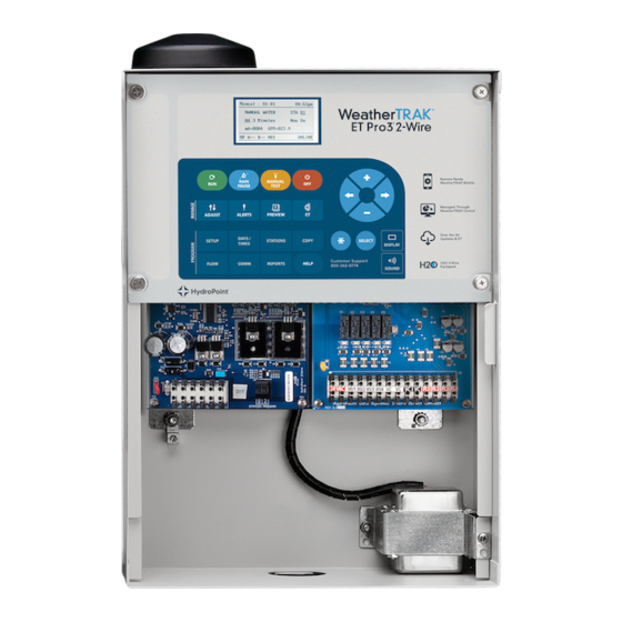
- Page 1 Featuring H2O Technology WeatherTRAK 2-Wire Controller Installation Guide Included in Guide: • 2-Wire System Overview • Installation Procedure • Grounding • Testing Questions? Contact Customer Support at support@hydropoint.com © Copyright 2020 HydroPoint Data Systems, Inc.
-
Page 2: Table Of Contents
2-Wire Status LED lights ..........................8 Hardware Installation ............................10 Installation Procedure ............................10 Step 1 — Install the WeatherTRAK 2-Wire Controller ................... 11 Mount the Enclosure: Wall Mounting Instructions ................. 11 Connect the Controller to AC Power ....................12 Insert Station Keys if Applicable ..................... - Page 3 Viewing Decoder Information ........................32 Viewing Electrical Information for Stations and Valves ................32 Troubleshooting .............................. 34 Standard Power and Current Readings...................... 34 Installed Decoders: Serial Numbers and Associated Stations Worksheet ............36 ©2020 HydroPoint Data Systems Inc. All rights reserved. 800.362.8774 • hydropoint.com...
-
Page 4: Overview
There are five major components to the WeatherTRAK 2-wire control system: the controller, the 2-wire path, the decoders, the accessories and the surge arrestors. The WeatherTRAK 2-wire controller The WeatherTRAK 2-wire controller is the main terminal point for all 2-‐wire paths as well as direct wire master valves and flow sensors. The 2-wire path The 2-‐wire path carries the power and control signals from the controller to the decoders and devices in the... -
Page 5: Weathertrak 2-Wire Devices
Total Supported Devices and Limits The following table lists the total numbers of devices by type that can be connected to a WeatherTRAK 2-wire controller. The WeatherTRAK 2-wire controller can support up to 110 device loads on the 2-wire path within the layout and length limits outlined later in this section. -
Page 6: Maximum Concurrent Valves
Maximum Concurrent Valves -#12 Wire Wire Length (ft) 1000-3000 4000 5000 6000 7000 8000 Maximum Concurrent Valves -#14 Wire Wire Length (ft) 1000 2000 3000 4000 5000 ©2020 HydroPoint Data Systems Inc. All rights reserved. 800.362.8774 • hydropoint.com... -
Page 7: Wire Specifications
Two-Wire Connection and programming Terminals 3 2-Wire connection terminals 1 decoder station programming push release terminal Other Terminals 3 Station Key ports 1 input rain sensor 1 Main 24VAC terminal ©2020 HydroPoint Data Systems Inc. All rights reserved. 800.362.8774 • hydropoint.com... - Page 8 WeatherTRAK 2-Wire Controller Installation Guide The diagram below shows where the terminals, connections and other parts are located. ©2020 HydroPoint Data Systems Inc. All rights reserved. 800.362.8774 • hydropoint.com...
-
Page 9: Led Light System
WeatherTRAK 2-Wire Controller Installation Guide LED Light System WeatherTRAK 2-wire controllers use an LED diagnostic light system to help with troubleshooting issues that may arise. Remove the controller front panel to completely reveal the valve and terminal boards. 2-Wire Status LED lights The 2-wire status LED lights turn red when an issue is encountered. - Page 10 Use the chassis diagram to identify each of the six LED diagnostic lights on the controller chassis and check to see if each is illuminated. Then, compare results to the diagnostic table below and take appropriate action. ©2020 HydroPoint Data Systems Inc. All rights reserved. 800.362.8774 • hydropoint.com...
-
Page 11: Hardware Installation
Installation Procedure The drawing below shows a typical two path wiring scenario with a master valve. The master valve can either be installed on the 2-‐wire path or directly to the WeatherTRAK 2-wire controller using a conventional wiring approach. ©2020 HydroPoint Data Systems Inc. All rights reserved. -
Page 12: Step 1 - Install The Weathertrak 2-Wire Controller
WeatherTRAK 2-Wire Controller Installation Guide Step 1 — Install the WeatherTRAK 2-Wire Controller Mount, electrically install and ground the WeatherTRAK 2-Wire Controller. Specifications can be found on our Product Details and Documentation page under Design Specifications for the ET Pro3 and the OptiFlow Controllers. -
Page 13: Connect The Controller To Ac Power
B. Connect the Controller to AC Power WARNING! Before making a connection to your WeatherTRAK 2-wire controller, disconnect the power to avoid electric shock. This installation should be made by a qualified electrician and should meet state and local electrical codes. -
Page 14: Insert Station Keys If Applicable
C. Insert Station Keys if Applicable The WeatherTRAK 2-wire controller incorporates station count modularity by using station keys. The station input/output boards are available in two configurations, 0-48 and 48-96. -
Page 15: Install A Rain Switch (If Applicable)
E. Install a Rain Switch (if applicable) The WeatherTRAK 2-wire controller is compatible with normally closed wired or wireless rain or rain/freeze switches. One rain switch can be shared with multiple controllers on a site. A dedicated 24 VAC output and Rain Sensor input terminal block is available on the terminal board (see terminal board diagram). - Page 16 Locate the rain switch transmitter within the manufacturer’s recommended range. Locate the transmitter where it will receive rainfall without obstruction. Confirm communication to the receiver before mounting permanently. ©2020 HydroPoint Data Systems Inc. All rights reserved. 800.362.8774 • hydropoint.com...
- Page 17 Two self- tapping stainless steel screws are taped to the inside of the enclosure to mount a rain sensor receiver when needed. Note: Mount the rain sensor receiver on the opposite side of the transformer location to avoid reception issues for wireless models. ©2020 HydroPoint Data Systems Inc. All rights reserved. 800.362.8774 • hydropoint.com...
-
Page 18: Step 2 - Assign Each Decoder To A Station
Step 2 — Assign Each Decoder to a Station After you have installed the WeatherTRAK 2-wire controller, you will need to assign the decoders to a station so the controller can find these stations in the field and activate the valve. -
Page 19: Assigning A Single Valve Decoder To A Station
Press + or – to set the power level. Power levels for each station can be adjusted independently. The power defaults to low. For most stations, low power is sufficient. ©2020 HydroPoint Data Systems Inc. All rights reserved. 800.362.8774 • hydropoint.com... -
Page 20: Assigning A Dual Valve Decoder To A Station
Note that the power defaults to low. For most stations, low power is sufficient. However, some stations may require more power due to a longer 2-wire path or a higher electrical requirement for a specific valve type. ©2020 HydroPoint Data Systems Inc. All rights reserved. 800.362.8774 • hydropoint.com... -
Page 21: Assigning A Master Valve, Flow Sensor Or Pump Start Decoder
However, some stations may require more power due to a longer 2-wire path or a higher electrical requirement for a specific valve type. ©2020 HydroPoint Data Systems Inc. All rights reserved. 800.362.8774 • hydropoint.com... - Page 22 However, some stations may require more power due to a longer 2-wire path or a higher electrical requirement for a specific valve type. ©2020 HydroPoint Data Systems Inc. All rights reserved. 800.362.8774 • hydropoint.com...
-
Page 23: Reassigning A Decoder
In the case where you have to reassign a decoder, simply disconnect the decoder in question and plug it into the Station Program terminal then repeat the decoder assigning process described above. ©2020 HydroPoint Data Systems Inc. All rights reserved. 800.362.8774 • hydropoint.com... -
Page 24: Programming A Direct Connect Master Valve
Plug the master valve wires into the ports located on the mini chassis board. Press SETUP. Press until CONFIGURE H2O 2-WIRE displays (setup 15). Press + or - to select Configure Direct Connect. Press SELECT to enter. ©2020 HydroPoint Data Systems Inc. All rights reserved. 800.362.8774 • hydropoint.com... -
Page 25: Programming A Direct Connect Flow Sensor
Plug the flow sensor wires into the ports located on the mini chassis board as illustrated above. Press SETUP. Press until CONFIGURE H2O 2-WIRE displays (setup 15). Press + or - to select Configure Direct Connect. Press SELECT to enter. ©2020 HydroPoint Data Systems Inc. All rights reserved. 800.362.8774 • hydropoint.com... -
Page 26: Step 3 - Install Valve Decoders Onto The 2-Wire Path
Press RUN to save and exit. Step 3 — Install Valve Decoders onto the 2-Wire Path Below is an illustration that details how a typical WeatherTRAK H2O decoder is installed. ©2020 HydroPoint Data Systems Inc. All rights reserved. 800.362.8774 • hydropoint.com... -
Page 27: Best Practices
Decoders are manufactured using color coded wires to help keep track of the wiring process. Below is a description of each type of decoder. Single Valve Decoder and Master Valve Decoder (WT2W-H2O-1VD) (WT2W-H2O-MV) Dual Valve Decoder (WT2W-H2O-2VD) ©2020 HydroPoint Data Systems Inc. All rights reserved. 800.362.8774 • hydropoint.com... - Page 28 WeatherTRAK 2-Wire Controller Installation Guide Flow Sensor Decoder (WT2W-H2O-FS) Pump Start Decoder (WT2W-H2O-PS) ©2020 HydroPoint Data Systems Inc. All rights reserved. 800.362.8774 • hydropoint.com...
-
Page 29: Step 4 - Ground The System
The WeatherTRAK 2-Wire controller should be protected through an AC surge protector on the primary incoming power to the controller. The WeatherTRAK 2-Wire controller provides a ground lug on the bottom front of the terminal board that accepts a #6 AWG bare copper wire that should be connected to a grounding system. - Page 30 Install a surge arrestor after valve box 1 and then just before valve box 2. Do not install any surge arrestors in-between. • Install grounded surge arrestors at every “dead end” that is 50 feet or longer. Below is a wiring diagram for a 2-wire controller system. ©2020 HydroPoint Data Systems Inc. All rights reserved. 800.362.8774 • hydropoint.com...
-
Page 31: Step 5 - Connect The Two--Wire Path To The Controller
Pres the button to underline and select the appropriate master valve (MV) or flow sensor (FS). Press the + or - button to change the setting to Direct Wired (DI) or 2-‐Wire (2W). ©2020 HydroPoint Data Systems Inc. All rights reserved. 800.362.8774 • hydropoint.com... -
Page 32: Step 7 - Program The Stations And Activate The Controller
Press the + or – button to select the number of minutes you would like to manually test for. Irrigation will begin immediately. The controller will immediately begin to irrigate stations 01 through the Max Active Stations for the selected runtime in numerical order. ©2020 HydroPoint Data Systems Inc. All rights reserved. 800.362.8774 • hydropoint.com... -
Page 33: Manual Test By Program
You can also view electrical information for each station, master valve, pump start or flow sensor to see how much electricity is being drawn. Viewing electrical information is done in the MANUAL TEST menu. Press MANUAL TEST. Press + or – until the diagnostics screen displays. ©2020 HydroPoint Data Systems Inc. All rights reserved. 800.362.8774 • hydropoint.com... - Page 34 Line 1: Screen number, time Line 2: Screen name Line 3: Decoder output number, On/Off, mA value per decoder. Line 4: Voltage in line, total value in mA for all decoders ©2020 HydroPoint Data Systems Inc. All rights reserved. 800.362.8774 • hydropoint.com...
-
Page 35: Troubleshooting
115-140mA. Note that these numbers are valid for decoders set to normal power. If you change the power settings, the numbers will change. The higher the power setting, the higher the current reading. ©2020 HydroPoint Data Systems Inc. All rights reserved. 800.362.8774 • hydropoint.com... - Page 36 Please refer to the WeatherTRAK Knowledge Base for articles specific to various 2-wire troubleshooting articles. ©2020 HydroPoint Data Systems Inc. All rights reserved. 800.362.8774 • hydropoint.com...
-
Page 37: Installed Decoders: Serial Numbers And Associated Stations Worksheet
Use the following worksheet to keep track of where your decoders are located and what their associated serial number is. For convenience, use the tear-off serial number sticker to attach to the worksheet page. Decoder Serial Number (sticker) Program Notes ©2020 HydroPoint Data Systems Inc. All rights reserved. 800.362.8774 • hydropoint.com... - Page 38 WeatherTRAK 2-Wire Controller Installation Guide Decoder Serial Number (sticker) Program Notes ST10 ST11 ST12 ST13 ST14 ST15 ST16 ST17 ST18 ST19 ST20 ST21 ST22 ST23 ST24 ST25 ST26 ST27 ©2020 HydroPoint Data Systems Inc. All rights reserved. 800.362.8774 • hydropoint.com...
- Page 39 WeatherTRAK 2-Wire Controller Installation Guide Decoder Serial Number (sticker) Program Notes ST28 ST29 ST30 ST31 ST32 ST33 ST34 ST35 ST36 ST37 ST38 ST39 ST40 ST41 ST42 ST43 ST44 ST45 ST46 ©2020 HydroPoint Data Systems Inc. All rights reserved. 800.362.8774 • hydropoint.com...
- Page 40 WeatherTRAK 2-Wire Controller Installation Guide Decoder Serial Number (sticker) Program Notes ST47 ST48 ST49 ST50 ST51 ST52 ST53 ST54 ST55 ST56 ST57 ST58 ST59 ST60 ST61 ST62 ST63 ST64 ST65 ©2020 HydroPoint Data Systems Inc. All rights reserved. 800.362.8774 • hydropoint.com...
- Page 41 WeatherTRAK 2-Wire Controller Installation Guide Decoder Serial Number (sticker) Program Notes ST66 ST67 ST68 ST69 ST70 ST71 ST72 ST73 ST74 ST75 ST76 ST77 ST78 ST79 ST80 ST81 ST82 ST83 ST84 ©2020 HydroPoint Data Systems Inc. All rights reserved. 800.362.8774 • hydropoint.com...
- Page 42 WeatherTRAK 2-Wire Controller Installation Guide Decoder Serial Number (sticker) Program Notes ST85 ST86 ST87 ST88 ST89 ST90 ST91 ST92 ST93 ST94 ST95 ST96 ©2020 HydroPoint Data Systems Inc. All rights reserved. 800.362.8774 • hydropoint.com...
- Page 43 WeatherTRAK 2-Wire Controller Installation Guide Notes ©2020 HydroPoint Data Systems Inc. All rights reserved. 800.362.8774 • hydropoint.com...
- Page 44 WeatherTRAK 2-Wire Controller Installation Guide Notes ©2020 HydroPoint Data Systems Inc. All rights reserved. 800.362.8774 • hydropoint.com...
- Page 45 WeatherTRAK 2-Wire Controller Installation Guide Notes ©2020 HydroPoint Data Systems Inc. All rights reserved. 800.362.8774 • hydropoint.com...
- Page 46 RevB20200715...
Need help?
Do you have a question about the WeatherTRAK 2-Wire and is the answer not in the manual?
Questions and answers