Table of Contents
Advertisement
Advertisement
Table of Contents

Related Manuals for HydroPoint WeatherTRAK ET Pro2


Summary of Contents for HydroPoint WeatherTRAK ET Pro2
-
Page 2: Table Of Contents
Table of Contents Key Features ..............1 Put WeatherTRAK ET Pro to work for you........1 How To Use This Manual ..........5 Need Help? ..............6 Contact WeatherTRAK Customer Service ........6 Flow Charts Explaining Your WeatherTRAK ET Pro Controller ......9 Chapter 1 ..............11 Getting To Know Your WeatherTRAK ET Pro ......11 Overview of Your WeatherTRAK ET Pro... - Page 3 Chapter 6 ..............55 Connecting a Grounding Wire to Your Controller ....55 Chapter 7 ..............59 Verifying Your Controller's Wiring ..........59 Testing Your Controller's Wiring..........60 Chapter 8 ..............63 Activating Your Controller ............63 About WeatherTRAK's ET Everywhere Service ......64 Contacting WeatherTRAK Customer Service......65 Activating Your Controller............65 Chapter 9 ..............73 Initial Setup Requirements ............73...
- Page 4 Chapter 13 ..............133 Using the Copy Function............133 Copying Station Data from One Station to Another ..134 Copying the Station Data from One Station to All Stations ..134 Copying Station Defaults to a Station ........135 Copying Program Defaults to a Specific Program ....136 Copying Setup Defaults to all Stations ......136 Chapter 14 ..............139 Flow Monitoring ................139...
- Page 5 Chapter 18 ..............185 ALERTS ..................185 Chapter 19 ..............199 Troubleshooting Guide ..............199 Water Window Alert ..............199 Water Day Alert ..............200 Communication Alert ............200 A Flow Alert Keeps Posting on One Station ......200 Valve Alert ................201 Display is Blank ..............201 The Controller Programs Correctly, but the Stations are Not Irrigating..............202 Landscape is Too Wet ............202 Landscape is Too Dry ............203...
-
Page 7: Key Features
Key Features Key Features Put WeatherTRAK ET Pro to work for you. Congratulations on selecting WeatherTRAK, the proven leader in smart irrigation. Twenty public agency studies and thousands of customers make it clear — WeatherTRAK is #1 for saving water, protecting landscapes, reducing runoff and satisfying customers. - Page 8 WeatherTRAK Customer Service Provides Customized Expertise Proactive support from our trained experts is a key component of the WeatherTRAK solution because satisfied customers are our first priority. Our team of horticulture and irrigation experts ensures that you always enjoy peak performance from your ET Pro Central or ET system.
- Page 9 Key Features...
-
Page 11: How To Use This Manual
How To Use This Manual How To Use This Manual The ET Pro Series uses 3 knobs and one button to perform all of the controller functions. There is a sequence or hierarchy of how these functions work. The MENU knob or largest knob in the center of the command module allows you to select any 1 of 16 controller functions. - Page 12 Button Note: This denotes an important note regarding a specific topic. The ET Pro has a unique function called a “submenu”. Submenus can be found in ALERTS, SERVICES, DAYS/TIMES and FLOW menus. The purpose of a submenu is to provide viewing or editing of a specific feature.
-
Page 13: Need Help
When complete with viewing Phase Integrities, turn the upper knob in either direction to go back to the main menu display screen shown below. VIEW PHASE INTEGRITY * Skip Turn the upper knob in either direction to scroll to the next or previous main menu display screen. - Page 14 Flow Charts Explaining Your WeatherTRAK ET Pro Controller WeatherTRAK lets you do everything you can do today with a conventional controller, plus so much more! Flow Charts Explaining Your WeatherTRAK ET Pro 2 Controller...
-
Page 15: Flow Charts Explaining Your Weathertrak Et Pro Controller
Conventional Control Product Station Programming Flow Charts Explaining Your WeatherTRAK ET Pro 2 Controller... -
Page 17: Chapter 1
Chapter 1 Getting to Know Your WeatherTRAK ET Pro In this chapter you will learn about: • Overview of your WeatherTRAK ET Pro controller • Overview of your WeatherTRAK ET Pro hardware • Selecting and adjusting settings Getting to Know Your WeatherTRAK ET Pro... - Page 18 WeatherTRAK ET Pro controller when your system is well-maintained. Install your new controller. HydroPoint recommends that you have the controller installed and programmed by an authorized WeatherTRAK ACE contractor. For more information, call WeatherTRAK Customer Service at (800) 362-8774.
-
Page 19: Overview Of Your Weathertrak Et Pro 2 Controller
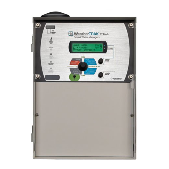
Overview of the WeatherTRAK ET Pro Controller The main controls of the WeatherTRAK ET Pro controller are: • Menu knob (1) • Upper knob (2) • Lower knob (3) • button (4) • The Menu List (5) • The three line display (6) The faceplate also includes two, 32-Pin connectors for optional handheld remote compatibility (7 and 8). - Page 20 Other non-prompted uses of are: • SETUP You can view hardware parameters like Max Active Stations identified versus found or installed. For example, if you have a 36 station controller and you have only implemented 28 of the stations, will display both values. This function is very useful for trouble-shooting.
- Page 21 WeatherTRAK service may be interrupted, either through a loss of communications with the HydroPoint service or from pending subscription expiration. Call WeatherTRAK Customer Service at (800) 362-8774. Note: If you cannot see the display in low or sunny conditions,...
- Page 22 SETUP This menu provides access to the following functions: • Adjust display contrast (for bright sunlight or low light levels) • Date (year) • Date (month) • Date (day) • Time (hour) • Time (minute) • Time zone • Auto daylight savings •...
- Page 23 STATIONS This menu provides access to the following functions: • Select station • Station mode • Select program • Use water window • Usable rainfall • Sprinkler type • Precipitation rate • Sprinkler efficiency • Soil Type • Plant Type •...
- Page 24 • Flow meter K and Offset values • Flow threshold values • Monitoring delay time For more information regarding the PREVIEW menu, see Chapter 16 “Other Programming Functions.” COPY This menu provides access to the following functions: • Copy data from one station to another station •...
- Page 25 • Measured Flow • Select flow meter mode • Edit excluded stations from No Flow • Set flow meter size • Edit flow K value (if different from factory default) • Edit flow offset value (if different from factory default) •...
- Page 26 For more information regarding the ET menu, see Chapter 15 “Evapotranspiration (ET).” SERVICES This menu provides access to the following functions: • For Customer Service phone number • Serial number WeatherTRAK ETPro2 version • • Phase integrity values • Lock phase •...
- Page 27 Getting to Know Your WeatherTRAK ET Pro...
-
Page 29: Chapter 2
Chapter 2 Overview of the Hardware The hardware of your WeatherTRAK ET Pro controller is comprised of the following components: • Power supply board • 12 station output/input board • 6 station output boards • Transformer • Ground lug • Hand-held remote module ports Overview of the Hardware... - Page 30 Power Supply Board (1) This printed circuit board provides 24-volt power to the station output boards as well as voltage to the command module and features a 3.0 amp sSlo fuse. Fig 2.1 Interior of wall-mount cabinet. Fig 2.2 Power PCB close-up. Overview of the Hardware...
- Page 31 12-station Output/Input Board (2) This printed circuit board contains 12 output terminals for operating valve wires, 1 valve common input, 1 master valve or pump start output, 1 flow meter input (2 terminals) and 1 rain sensor input (2 terminals). Each station output has a LED that will illuminate when the station is operating either manually, during scheduled irrigation and during a valve check.
- Page 32 Fig 2.4 Ground wires. Power Supply (4) This is an 80VA, 3.0 amp, dual-voltage power supply for usage with 120 volts of 220 volts, (single phase) AC power applications. Ground Lug (5) This ground lug provides additional earth ground protection of electronic components when specified or where the incidence of ground strikes from lighting is high.
-
Page 33: Selecting And Adjusting Settings
Selecting and Adjusting Settings You can select and adjust the controller's settings in three simple steps: Turn to any desired menu. • • SETUP • DAYS / TIMES • STATIONS • PREVIEW • COPY • % ADJUST • ALERTS • FLOW •... - Page 34 Settings and Adjustments Example: Adjusting the Display Contrast Turn to SETUP. Turn one position. Turn until you find the desired screen contrast. The display shows this: ADJUST DISPLAY CONTRAST An underlined value in the first or second line of the display is a value that can be changed.
- Page 35 Overview of the Hardware...
-
Page 37: Chapter 3
Chapter 3 Installing the Controller This chapter provides instructions for installing the WeatherTRAK ET Pro controller. In this chapter you will learn how to: • Select the correct location for your controller • Install your controller Installing the Controller... -
Page 38: Selecting The Correct Location For Your Controller
Selecting the Correct Location for Your Controller The location of your WeatherTRAK ET Pro controller may be based on landscape irrigation plans or by the termination point for valve station wires. If you can select the controller location, consider some of the guidelines listed below when determining where to place your WeatherTRAK ET Pro controller:... -
Page 39: Installing Your Controller
Installing Your Controller For Wall Mount Enclosures Wall mount enclosures have four mounting holes located 16” on- center. Mark the upper holes verifying the controller is plumb and level in two directions. Use galvanized lag screws or other fasteners of sufficient length and diameter to secure the enclosure to a vertical wall, (see Figure 3.1). - Page 40 Fig 3.2 Pedestal enclosure mounting holes. Mounting template w/ threaded studs not shown. Note: The display contrast can be adjusted if needed under the SETUP Menu. Prior to pouring of the concrete pad, stub out the various conduits and sizes are required for: •...
- Page 41 Installing the Controller...
-
Page 43: Chapter 4
Chapter 4 Connecting the Controller to AC Power In this chapter you will learn about: • Connecting AC Power to Wall Mount Controllers • Connecting AC Power to Pedestal Controllers This chapter also includes: • Photos for wiring 120 Volt Connections •... - Page 44 Note: Before making a connection to your WeatherTRAK ET Pro controller, disconnect the power to avoid electric shock. This installation must be made by a qualified electrician and must meet state and local electrical codes. Connecting Power to Wall Mount Controllers Fig 4.1 120-volt Wall-mount.
- Page 45 Locate the threaded 1/2” nipple for the controller's transformer on the underside of the enclosure (for wall mount enclosures or chassis models). Locate the junction box mounted on the backpanel for pedestal models. Thread an approved plastic or galvanized metal junction box onto the 1/2”...
-
Page 46: Wiring Diagrams For 120 Volt Connectors
Wiring Diagrams for 120 Volt Connectors Fig 4.3 120-volt connector wiring. Note: For 120 volt wire connections, connect the following conductors from the primary side of transformer to wiring back to an electrical source: (see Figure 4.4). Blue Not used. Clip off exposed conductor and terminate with a wire nut. -
Page 47: Wiring Diagrams For 220 Volt Connectors
Wiring Diagrams for 220 Volt Connectors Fig 4.4 220-volt connector wiring. Note: For 220 volt, single-phase connections connect the following conductors from the primary side of the transformer to wiring back to an electrical source: (see Figure 4.5). Blue White Green Ground Brown... - Page 48 Note: Do not bypass the fuse or replace the fuse with a higher rated fuse. Serious damage can occur to the controller including fire or other property damage. Fig 4.5 Always adhere to local electrical codes. The ground wire should be terminated with an appropriate sizedeyelet (enclosed) and secured with a nut with integral star washer located within the junction box.
- Page 49 Connecting the Controller to AC Power...
-
Page 51: Chapter 5
Chapter 5 Connecting Your Controller to Stations and Other Field Accessories In this chapter you will learn how to: • Connect field wires to your controller • Connect a hand-held remote to your controller • Connect a rain sensor to your controller •... -
Page 52: Connecting Field Wires To Your Controller
Connecting Field Wires to Your Controller The WeatherTRAK ET Pro controller can manage between 12 and 48 stations including separate inputs for a pump/master valve, a flow meter, or a rain, rain/freeze, or wind sensor. Fig 5.1 Overstripped wire in the center. Fig 5.2 Example of over-stripped wire could lead to valve shorts. - Page 53 The controller provides all station outputs on one horizontal plane for faster installation and troubleshooting. If remote control wires are installed in the incorrect sequence or changes are needed at a later date, the wires can simply be moved from one position to another without the need to make a splice or remove excess wire.
-
Page 54: Connecting A Hand-Held Remote To Your Controller
Confirm the small black lever of the corresponding terminal is up or in the open position. Insert the exposed conductor into the terminal hole and press the black lever into a closed position. Note: Avoid pushing the wire with insulation into the terminal opening to the point where the locking mechanism clamps on the insulator and not the conductor. - Page 55 Fig 5.4 Handheld installation. As an after-sales accessory, there are two model numbers of Remote Control Interface upgrade kits depending on the size of the enclosure and number of stations listed as: • 42-stations WTEXB-PRO2-42RI • 48-stations WTEXB-PRO2-48RI Note: Hand-held remote kits can be purchased through your local irrigation distributor.
- Page 56 Note: Any wireless rain sensor will require the receiver to be installed on outside of any enclosure to ensure consistent reception from a remotely mounted rain sensor. To connect a wireless rain sensor to your controller: Mount the rain sensor receiver where it can be observed. Route the receiver wires through approved conduit into the interior of the enclosure.
- Page 57 Fig 5.6 Rain sensor loop. Remove approximately 3/8” of the wire insulation to expose the wire conductor. These terminals have bipolarity that will accept either 24-volt wire from the rain sensor receiver. Ensure that the locking lever of the screw-less terminal is in the open position (see Figure 5.6).
- Page 58 Note: Do not locate the rain sensor under a tree canopy or eave of a roof. Install the sensor wire in a protective conduit that is terminated within the interior of the enclosure. Locate the rain sensor input terminal block in the middle of the 12-station input/output PCB, (see Figure 5.7).
- Page 59 Testing Flow Meter Run any station manually, once the flow information has been setup in the FLOW menu to verify that data can be monitored. If there is no flow observed in “Measured Flow”, recheck the wire connections and flow setup menus, then repeat the process to confirm flow monitoring.
-
Page 61: Chapter 6
Chapter 6 Connecting a Grounding Wire to Your Controller In this chapter you will learn how to: • Connect a grounding wire to your controller Additional ground may be specified or because regional practices require additional protection to controller electrical components due to the high incidence of lighting ground strikes. - Page 62 To connect a grounding wire to your controller, do the following: Install a 3/4” conduit (minimum) from the bottom of the enclosure below grade away from incoming AC power wires, remote control wires and sensor wires. Use a minimum of a 12” radius sweep when direction changes are necessary and avoid any sharp turns or bends in the conductor to a ground rod or ground plate.
- Page 63 Verify a resistance of 10 ohms or less with a megger or other suitable ground measuring device. If ohms resistance is above this value, additional ground rods or plates may be required. Note: Avoid one ground conductor sharing more than one ground rod or plate.
-
Page 65: Chapter 7
Chapter 7 Verifying Your Controller's Wiring In this chapter you will learn how to: • Test the your controller's wiring Verifying Your Controller’s Wiring... -
Page 66: Testing Your Controller's Wiring
Testing Your Controller's Wiring Prior to activation or initial programming it might be helpful to confirm electrical continuity to all valve stations, master valve and any sensor wires. The WeatherTRAK ET Pro controller has a Valve Test feature in the SERVICES menu that can be used specifically for this purpose. To test your controller's wiring: Turn to SERVICES. - Page 67 Turn to view successive screens. Each screen will display the data for eight stations at a time up to the total number of stations within the controller. In the event of an error, first check the connections to the solenoid on the specified station.
-
Page 69: Chapter 8
Chapter 8 Activating Your Controller In this chapter you will learn about: • WeatherTRAK's ET Everywhere service • Contacting WeatherTRAK Customer Service • Activating your controller Activating Your Controller... -
Page 70: About Weathertrak's Et Everywhere Service
About WeatherTRAK's ET Everywhere Service After you have finished installing your WeatherTRAK ET Pro controller, you are ready to activate the controller with WeatherTRAK's ET Everywhere service. Activation of your ET Everywhere service ensures: • Adequate signal strength is being received •... -
Page 71: Contacting Weathertrak Customer Service
Contacting WeatherTRAK Customer Service To activate your controller, call WeatherTRAK Customer Service at (800) 362.8774 This process will only take a few minutes. WeatherTRAK Customer Service Hours of Operation are: 7:00 am to 6:00 pm Monday through Friday during Daylight Savings Time. 7:00 am to 5:00 pm Monday through Friday during Pacific Standard Time. - Page 72 If this is the case, a higher gain antenna is recommended to ensure reliable communication. Various external antenna kits are available through HydroPoint Data Systems depending on site requirements including aesthetics as well as required signal strength to ensure consistent communication.
- Page 73 Note: This function is only used when ET Everywhere Service is activated. Once activation is complete, all phase are live and will be used to receive daily ET updates. Locking on a phase during the activation expedites this process. At midnight on the day of activation, the controller will automatically unlock the selected phase.
- Page 74 ET SUBSCRIPTION EXPIRES: 01-01-07 This screen displays when your ET subscription service will expire. Note: The WeatherTRAK Pro Series controller will automatically prompt you when as the subscription date is within 60, 45, 30 and 15 days of expiration. To maintain optimum plant health and consistent water savings, WeatherTRAK recommends that you keep your ET Everywhere subscription up-to-date.
- Page 75 13. Turn to Days Since Last ET. This is a view only screen and shows when the last ET Everywhere message was received. The display shows this: DAYS SINCE LAST ET If you are activating for the first time, the value will be zero. This value will not change until after midnight of the next day.
- Page 76 This feature allows you to quickly run through each station output and master valve to verify electrical continuity. • The test is automatic and takes approximately 10-15 seconds. • To skip this test, simply turn to complete activation. • To run this test turn one click.
- Page 77 Activating Your Controller...
-
Page 79: Chapter 9
Chapter 9 Initial Setup Requirements In this chapter you will learn how to: • Configure primary setup functions • Configure secondary setup functions Note: WeatherTRAK ET Pro delivers optimal performance when accurate landscape-specific information is entered and your irrigation system is free of defects (e.g., cracked pipes and broken sprinkler heads). Note: The Installation and Program Settings worksheet serves three purposes;... -
Page 80: Configuring Primary Setup Functions
Configuring Primary Setup Functions Once you have activated your WeatherTRAK ET Pro controller, you are ready to make some initial configurations. These include: • Set the date and time • Set the time zone • Set the maximum active stations •... - Page 81 Setting the Month Turn until the display shows this: DATE (MONTH) Jan 10 2006 The default month is “Jan” (January). Turn to select the current month. Setting the Day Turn until the display shows this: DATE (DAY) Jan 01 2006 The default day is “01.”...
- Page 82 Setting the Time (Minute) Turn until the display shows this: TIME (MINUTE) 12:01am The default time is “12:00 a.m.” Turn to select the current minute. Setting the Time Zone Turn until the display shows this: TIME ZONE Pacific The default time zone is “Pacific.” This function allows the following time zones: •...
- Page 83 This value should correspond to the actual number of valve stations that are going to be programmed by the controller. Turn to set the station count between 1-48 stations. Note: If you set Max. Active Stations to a value higher than the actual number of valves connected, you may add unnecessary time to the watering window.
- Page 84 To Set the Stack or Overlap Mode Turn until the display shows this: STACK or OVERLAP Stack Your WeatherTRAK ET Pro can operate in one of two ways depending on the hydraulic capacity, delivery pressure and other flow characteristics of your system. •...
-
Page 85: Configuring Secondary Setup Functions
The WeatherTRAK ET Pro controller features a dedicated master valve/pump start output as a standard feature. The master valve is used to isolate the mainline or a portion of the mainline when programmed as part of flow monitoring. It enables your WeatherTRAK ET Pro controller to troubleshoot and isolate pipe malfunctions or other types of failures. - Page 86 When you are completed with your adjustments, turn to RUN. Selecting Auto Daylight Savings Your WeatherTRAK ET Pro controller is set to daylight savings time by default to ensure that the controller will keep accurate time corresponding to the previously selected time zone and daylight saving standard.
- Page 87 The default value for this function is “No.” When set to “Yes”, your WeatherTRAK ET Pro controller will run a valve test each time a station begins irrigation. When a valve fault is found it will trigger a valve alert message notifying you of a problem. To change the value, turn to yes.
- Page 88 Turn until the display shows this: MAX BACKUP ET PART 2 2.00 Turn to change the value to the right of decimal point. To complete this process, turn to RUN. Initial Setup Requirements...
- Page 89 Initial Setup Requirements...
-
Page 91: Chapter 10
Chapter 10 Definition of Terms Automated by WeatherTRAK Automated by WeatherTRAK is an exclusive Program Mode that will automatically calculate run times, cycle and soak periods, from user- defined site-specific data on a station-by-station basis. WeatherTRAK's exclusive Scheduling Engine reflects the Irrigation Association's (IA) best management practices (BMP's) for irrigation scheduling. - Page 92 types and cannot be modified. For more information, see chapter 15 “Evapotranspiration (ET).” Max. Active Stations Max. Active Stations is the maximum number of stations actually programmed. This is not the maximum number of stations within a controller. For example, if the controller size is programmed to run 33 stations, although the controller has 36 station outputs, the maximum number of stations would therefore be 33.
- Page 93 Program WeatherTRAK offers four programs — A, B, C and D. Each program can be assigned a start time, up to 20 cycles, one of seven water day patterns and a second start time for High ET when applicable. Programs are assigned on a station-by-station basis. Each station can only be assigned one program.
- Page 94 Rain Service Rain Service is an optional service to automatically suspend scheduled irrigation based on raunfall amounts. This is a separate service that can be activated in addition to ET Everywhere and is available on a limited basis throughout the United States. To determine If Rain Service if available for your area, call your WeatherTRAK Customer Service representative (800) 362-8774.
- Page 95 Soil Type The United State Agriculture Administration has classified soil texture into 5 classifications. Each of the 5 classifications has different infiltration or percolation rates and well as water-holding capacities. These soil types and known infiltration rates are used as part of calculating run times as well as cycle and soak times when using the Automated by WeatherTRAK program mode.
- Page 96 defined water window by program and the ability to water within or outside of the water window. The WeatherTRAK ET Pro has two start times per program each with user-defined water windows from 1 to 23 hours and 59 minutes. For more information see Chapter 11 “Minimum Programming Requirements.”...
- Page 97 Definition of Terms...
-
Page 99: Chapter 11
Chapter 11 Minimum Programming Requirements This chapter explains the minimum programming requirements to configure your WeatherTRAK ET Pro controller for either a new landscape or an existing landscape. In this chapter you will learn how to: • Select a program •... -
Page 100: Selecting A Program
Selecting a Program Your WeatherTRAK ET Pro has four separate programs to choose from: A, B, C and D. Stations can be individually assigned to one of the 4 programs. Each program has specific modes, start times and watering windows. For more information on assigning stations to programs see Chapter 12 “Assigning Stations to a Program.”... - Page 101 Set Starts/Windows Programs can have watering windows of 1 hour to 23 hours and 59 minutes. Water windows are exclusive to their assigned programs and will not impact the water windows of other programs. Your WeatherTRAK ET Pro controller will automatically calculate the end time based on the start time and the length of the water window.
- Page 102 Note: If you leave STARTS/WINDOW submenu and you have an “Overlap” warning, none of the changed value will be saved and the default settings will remain in place. If “Edit” is selected the next screen to appear will allow you to enter the 1st start time and water day.
- Page 103 Turn until the display shows this: Turn to change the minute value. Turn to scroll to the next screen. Otherwise, turn to RUN to complete this process. Selecting a Watering Window (Hour) To Select a Watering Window (Hour) Turn to DAYS/TIMES. Turn until the display shows this: 1ST START/Window PRG A...
-
Page 104: Assigning A Second Start Time
Turn to scroll through the water window “minute” settings for the selected program. You can choose values from 1-59. Turn to scroll to the next screen to complete your selection. Note: Watering windows less than 1 hour cannot be selected. Note: The maximum watering window is 23 hours and 59 minutes. - Page 105 2nd START TYPE PRG A High ET Only (Button to View) The choices are “Off” (default) or “High ET Only.” Turn to select “High ET Only.” SET STARTS/WINDOW PRG A Skip (Button to View) Note: If you don't want to use the Second Start Time feature, you can leave it in its default off position by turning to scroll to the next screen.
- Page 106 To Set the High ET Start (Hour) Turn until the display shows this: Turn to scroll through the Second Start hour settings for the selected program. You can choose values from 1st start times end time to 12pm with “7:00pm” being the factory default.
- Page 107 Note: The Water window range for the second start time is 23 hours 59 minutes. If the second start time is after midnight with the odd/even day Water Day Mode option active, the controller will not irrigate. In this case, set the second start time to prior to midnight and the controller will complete the irrigation cycle.
- Page 108 Turn to scroll through the Second Start water window length hour settings for the selected program. You can choose values from 1-23 hours. The factory default water window is 1 hour and the maximum water window length is 23 hours and 59 minutes. Turn to scroll to the next screen to complete your selection.
-
Page 109: Assign A Water Day Pattern To A Program Mode
Assign a Water Day Pattern to a Program Mode The WeatherTRAK ET Pro has seven different water day patterns to choose from: • Optimized by WeatherTRAK — the pattern in which the watering days are automatically determined for each station as its individual depletion value reaches 50%. -
Page 110: Assigning The Auto Day Exclusion Option (Optimized By Weathertrak Water Day Mode Only)
To Choose a Water Day Pattern Turn to DAYS/TIMES. Turn until the display shows this: WATER DAY MODE PRG A Optimized by WeatherTRAK Turn to scroll through the selections of water day patterns until you find one that suits your requirements. Assigning the Auto Day Exclusion Option (Optimized by WeatherTRAK Water Day Mode Only) In some locations water conversation measures prohibit irrigation on... - Page 111 Turn until the display shows this: DAY EXCLUSION PRG A None Turn to scroll through the days of the week. The choices are: • None, • Sunday, • Monday, • Tuesday, • Wednesday, • Thursday • Friday, • Saturday In this water day mode, only one day per week can be excluded. For all other remaining program modes (except Off), additional days can be excluded from irrigation as needed.
-
Page 113: Chapter 12
Chapter 12 Assigning Stations to a Program This chapter explains how to: • Assign stations to a program in a new landscape • Assign stations to a program in an existing landscape • Preview station data Note: The WeatherTRAK ET Pro features a Copy function to speed up programming time. -
Page 114: To Assign Stations To A Program In A New Landscape
To Assign Stations to a Program in a New Landscape In this section you will: • Select a station • Assign the station to a station mode • Assign the station mode to a program (with a start time, water window, water day pattern) To Select a Station Turn... - Page 115 Character Display Station Modes Auto Automated by WeatherTRAK User defined with ET USER User defined without ET Turn to scroll to the next screen to complete your selection. To Assign a Station to a Program (A, B, C, D) Turn to STATIONS.
- Page 116 Turn until the display looks like this: USE WATER WINDOW STA 01 Yes (end time 03:01am) You have two choices in this function: • Yes — use to the water window established • No — ignore this programming parameter. Your WeatherTRAK ET Pro controller is configured to use the pre-programmed water window by default.
- Page 117 USABLE RAINFALL STA 01 100% The default is “100%” and the choices are as follows: • None, • 25%, • 50%, • • 100% If a portion of rainfall is to be used, turn until the desired percentage is displayed. Turn to scroll to the next screen.
- Page 118 To Set Station Run Time (Tenths) Turn to STATIONS. Turn until the display looks like this: RUN TIME PART 2 STA 01 05.0 Minutes To skip the next selection and move to the next screen, turn To adjust a run time in 10ths, turn until the desired fraction is displayed.
- Page 119 To Set the Soak Time Between Cycles The delay time between cycles is also user-defined from 10 minutes to 480 minutes in 10-minute increments. Turn to STATIONS. Turn until the display looks like this: SET SOAK TIME STA 01 30 Minutes The default is “30”...
- Page 120 Turn until the display looks like this: REFERENCE ET PT1 STA 01 1.00 (Weekly ET 1.00) The default is 1” per week. Turn to the first valve from 1” to 3”. You cannot select 0” in this screen unless another value exists in the hundredths position.
-
Page 121: To Assign Stations To A Program For An Existing Landscape
Turn to scroll from January through December until the desired reference month is found. Note: Reference ET allowable range is between 0.50 and 3.99. Note: To set a Reference ET less than 1, first set the decimal value between “50” and “99” before setting the digit value in Part 1 to “0”. - Page 122 • Set root depth • Set the Microclimate • Set the degree of slope • Select sprinkler location Note: The WeatherTRAK ET Pro is one of a few controllers with a Copy function to speed up programming time. If a site has many stations with similar watering times and other requirements, the Copy function can be used to greatly simplify programming time.
- Page 123 Line 3 Character Display Meaning WK2: 2nd week's water day pattern S-T-T-S Week 1 irrigates on Sunday, Tuesday, Thursday, Saturday To Select a Station Turn to STATIONS. The display will look like this: SELECT STATION Turn to scroll to the required station. Turn to scroll to the next screen.
- Page 124 To Assign a Station to a Program Turn to STATIONS. Turn until the display shows this: SELECT PROGRAM STA 01 A (Optm S12:01am W3:00) The selected station can now be assigned to any one of four programs noted as: Character Display Program Turn to scroll through the four programs.
- Page 125 You have two choices in this function: • Yes - use to the water window established • No - ignore this programming parameter. Your WeatherTRAK ET Pro controller is configured to use the pre-programmed water window by default. To preserve the default value, to skip to the next display.
- Page 126 The character display for this function is: Character Display Usable Rainfall None 100% If a portion of rainfall is to be used, turn until the desired percentage is displayed. Turn to scroll to the next screen. To Configure a Run, Cycle and Soak Times in Automated by WeatherTRAK Station Mode In this mode, the next 10 screens will ask you to select site-specific landscape attributes for the station you have selected.
- Page 127 Turn to STATIONS. Turn until the display shows this: SPRINKLER TYPE STA 01 Spray Head The character display for this function is: Character Display Sprinkler Type Spray Head Full Circle Rotor Part Circle Rotor Mixed Rotors Full Circle Impact Part Circle Impact Mixed Impacts Stream Rotors Bubbler...
- Page 128 PRECIP PART 1 STA 01 1.70 Inches/Hr (default) The value for precipitation rate is given in the following format 1.00, in Part 1 you edit the first value from 1 to 9 in 1” increments. To edit the first value, turn until the desired value is displayed.
- Page 129 sprinkler type selected. The sprinkler efficiency can be modified from 10% to 95% in 5% increments. Turn to STATIONS. Turn until the display shows this: SPKLR EFFICIENCY STA 01 70 Percent (default) To edit the efficiency, turn to the desired value. Turn to scroll to the next screen.
- Page 130 SOIL TYPE STA 01 Sandy The character display for this function is: Character Display Soil Type Sandy Sandy Loam Loam Clay Loam Clay Turn to scroll through the choices. Turn to scroll to the next screen. Note: If the soil type can be readily determined, use the “ribbon-test”...
- Page 131 • Mixed - High water use • Mixed - Medium water use • Mixed - low water use • Native Shrubs / Trees • Native Grasses • Custom Plant A • Custom Plant B • Custom Turf For more information on sample plant types, see “Appendix B: Typical Plant Types and Root Depths.”...
- Page 132 Turn to scroll through the list of plant types. Turn to scroll to the next screen. To Set Root Depth Each plant type has a default root depth. Typically the root depths represent established plant material. Root depths can be set on a station-by-station basis.
- Page 133 The WeatherTRAK ET Pro offers four choices of Microclimates listed as: • Sunny All Day (default) • Sunny Most of the Day • Shady Most of the Day • Shady All Day Turn to STATIONS. Turn until the display shows this: MICROCLIMATE STA 01 Sunny All Day...
- Page 134 • Moderate 13-20% Grade • Steep >20% Grade Similar to all previous site attributes, this value is selected on a station-by-station basis. Turn to STATIONS. Turn until the display shows this: SLOPE FACTOR STA 01 None/Slight 0-5% Grade The character display for this function is: Character Display Degree of Slope None/Slight 0-5% Grade...
- Page 135 Turn until the display shows this: SPRINKLR LOCATION STA 01 None, No Slope Set The character display for this function is: Character Display Sprinkler Location of a Slope All Parts of Slope Top of Slope Middle of Slope Bottom of Slope If the default value is correct, turn to scroll to the next screen.
-
Page 136: Previewing Station Data
Note: To preview a station's run time, cycle and soak periods, turn to PREVIEW. For more information on the PREVIEW menu, see Chapter 16 “Other Programming Functions.” Previewing Station Data Once a station's data is entered, the previously selected parameters can easily previewed by pressing once. - Page 137 Line 2 (continued) Character Display Meaning Abbreviated microclimate (Shady Most of the Day) Abbreviated slope (Gentle) Abbreviated location of slope (Sprinklers Located on Top of Slope) Usable rainfall (25%) For more information on the PREVIEW menu, see Chapter16 “Other Programming Functions.” Assigning Stations to a Program...
-
Page 139: Chapter 13
Chapter 13 Using the Copy Function This Chapter explains how to: • Use the Copy function. The copy function is unique to the WeatherTRAK ET Pro controller. It can be used to: • Copy station data from one station to another •... -
Page 140: Copying Station Data From One Station To Another
Copying Station Data from One Station to Another To copy station data from one station to another Turn to COPY. Turn until the display shows this: COPY FROM STA 01 TO STA 02 (Press Button) Turn to scroll through stations 01 to Max. Active Stations (set in Setup). -
Page 141: Copying Station Defaults To A Station
COPY FROM STA 01 TO ALL STA's (Press Button) Turn to scroll from station 01 to the Max Active Stations. Press and hold for 2 seconds until the display shows this: COPYING… DONE! Turn to RUN to complete this process. Copying Station Defaults to a Station To Copy Station Defaults to all Stations Turn... -
Page 142: Copying Program Defaults To A Specific Program
Copying Program Defaults to a Specific Program To Copy Program Defaults to a specific Program Turn to COPY. Turn until the display shows this: COPY PROGRAM DEFAULTS TO PGM A (Press Button) Turn to scroll through programs A, B, C or D. Press and hold for 2 seconds until the display shows this: COPYING…... - Page 143 To copy station defaults to all stations, press and hold for 2 seconds until the display shows this: COPYING… DONE! Using the Copy Function...
-
Page 145: Chapter 14
Chapter 14 Flow Monitoring In this chapter you will learn about: • WeatherTRAK ET Pro flow monitoring hardware requirements • Flow monitoring capabilities • Configuring flow functionality Flow Monitoring... -
Page 146: Weathertrak Et Pro 2 Flow Monitoring Hardware Requirements
WeatherTRAK ET Pro Flow Monitoring Hardware Requirements Your WeatherTRAK ET Pro controller is capable of flow monitoring, response and alert notification as a standard feature. The minimum hardware requirements for this feature are: • A flow sensor • A two-wire communication path from the flow sensor back to the controller. -
Page 147: Weathertrak Et Pro 2 Flow Monitoring Capabilities
WeatherTRAK ET Pro Flow Monitoring Capabilities Your WeatherTRAK ET Pro controller monitors for the following flow conditions: • High flow or a catastrophic mainline failure • Leak detection during scheduled irrigation soak times as well as non-irrigation schedules. • No flow monitoring during scheduled irrigation. Each flow condition shall ahve its own user defined threshold including “off”, as well as “monitoring delay time period”. -
Page 148: Configuring Flow Functionality
No Flow When the controller is running a scheduled irrigation program by electrically opening a valve and no flow is observed by the flow sensor, the controller will wait for one minute. If no flow has occurred within this timeframe, the controller will close the valve and will move to the next valve in the programming sequence. - Page 149 Note: The can be pressed anytime in the FLOW menu to view Measured Flow. If water is currently operating manual or from an irrigation schedule, the real time flow is displayed and updated for each pulse received from the flow meter. Press and hold view the following screen.
- Page 150 Select Flow Meter Mode Turn until the display shows this: FLOW METER MODE In this screen you may only select the FM1 value (in future releases additional flow meters will supported). Turn to scroll to the next screen. Note: If flow meter is off, next screen will show “Menu Complete”. To Exclude Stations In some instances the flow range of system hydraulics can be such that some valves with low GPM requirements are below the...
- Page 151 The default setting is “Y,” or yes, to monitor flows for each station. Turn to scroll through each station and turn to change the value to exclude a station. A value of “Y” means that the corresponding station will be monitored while a value of “N”...
- Page 152 Note: If you change the K or Offset value, then select another flow meter size the user-defined value will remain. If you maintain the default K or Offset value and select another flow meter size, the default value for the associated flow meter size will also change. To Edit a “K”...
- Page 153 Note: The default K value for your flow controller will be displayed in the ( ) and will remain unchanged. After moved through all decimal places, turn to move to the next screen. To View/Edit Offset Value Editing the default Offset value is the same as editing the K Value except the first selection determines if the value is positive (+) or a negative (-) number.
- Page 154 Note: The default value can be seen in ( ) and will remain unchanged. In the next few screens, you can define the flow thresholds for high- flow, no-flow and leak detection. If you choose not to set a particular flow parameter, you may select Off by turning the knob until you see the word “Off”.
- Page 155 To enter a different High-Flow threshold value, to until you see this display. HIGH FLOW THRESHOLD 015 GPM 0 Minutes Turn the to increase or decrease the desired flow value. The Alert can be disabled by turning counter clockwise from “001 GPM”, at which time “Off”...
- Page 156 The No Flow threshold value should represent a value10-15% higher than the GPM requirement of the smallest valve demand. The default No Flow value is “001 GPM” which can be edited from as little as 1 to 30 GPM in 1 GPM increments and 30 to 995 in 5 GPM increments.
- Page 157 Turn the to increase or decrease the desired flow value. Turn the to scroll to the next screen. To Set Leak Detect Monitoring Delay Turn until the display shows this: LEAK DETECT DELAY 015 GPM 3 Minutes The monitoring delay period can be set from 1–6 minutes in 1-minute increments.
-
Page 159: Chapter 15
Chapter 15 Evapotranspiration (ET) In this chapter you will learn how to: • View your controller's ET information • Adjust crop coefficients (Kc) for custom plants • Adjust crop coefficients (Kc) for custom turf • Set Month and Weekly Reference ET when User w/ ET station mode is used. -
Page 160: Viewing Your Controller's Et Information
Viewing Your Controller's ET Information Your WeatherTRAK ET Pro controller provides the ability to view ET data as follows: • View ET on a daily basis, • View average weekly ET To View Daily ET Turn to ET. Turn until the display shows this: CURRENT DAILY ET 0.14 01-01-05 03:00:00am This is a view only display and cannot be edited. -
Page 161: Adjusting Kc For Custom Plants
This is a view-only screen and cannot be edited. The average weekly ET is sum total of last seven days ET value divided by seven. Note: If a week of ET data has not been collected, then the daily ET data available will be averaged and will represent average weekly Adjusting Kc for Custom Plants Your WeatherTRAK ET Pro controller provides the flexibility to set... -
Page 162: Adjust Kc For Custom Turf
To increase or decrease the Kc value turn until the adjusted value is displayed. Turn to RUN to complete the process. Adjust Kc for Custom Turf The Custom Turf Kc value can be edited on a monthly basis as needed. Custom Kc's for turf could be used for specialty grasses such as Buffalo or Pennisetum grasses used in cultured landscapes. -
Page 163: Irrigating Based On User-Defined Et
Setting the controller to do this is a two-step process where step one changes the digit to the left of the decimal point in the ET value and step two changes the two digits to the right of the decimal point. This feature can be used if you want to view how a schedule will change based on a higher or lower ET value that what is being received. - Page 164 ET Menu Complete The last screen in this menu is the complete screen that appears as shown. ET MENU COMPLETE Turn to RUN to complete this process. Evapotranspiration...
- Page 165 Evapotranspiration...
-
Page 167: Chapter 16
Chapter 16 Other Programming Functions In this chapter, you will learn about the following menu options: • PREVIEW • REPORTS • MANUAL • % ADJUST • RAIN OPTIONS • ADVANCED • SERVICES • Other Programming Functions... -
Page 168: Preview
PREVIEW The PREVIEW menu provides a fast and easy way to preview all station programming parameters as well as flow parameters if flow values are setup. All of the screens in the PREVIEW menu are view only and cannot be edited. The PREVIEW menu provides the following functions: •... - Page 169 Station Preview Station Preview lets you view an individual station's programs on an eight-week go-forward basis. This is very useful if your landscape includes native or specialty plants on a long Interval or Optimized cycle. In both examples a particular station or stations may not water for several weeks at a time.
- Page 170 Line 2 Character Display Meaning WK1: Week 1 up to 8 weeks S-T-T-F Water day pattern +15% % Adjust Soak Soak time between cycles Minutes Note: If a station has been turned off, the display will show the following: ST01 View Flow Data If Flow Data is selected the first screen to appear is show below.
- Page 171 Turn until the display shows this: MASTER VALVE STATUS Normally Closed/Pump On Turn to view the next screen. View Excluded Stations This function displays the list of stations that have been excluded from flow monitoring, To View Excluded Stations While in Flow Data in the Preview Mode function, turn until the display shows this: VIEW EXCLUDED STATIONS Skip...
- Page 172 Turn to view the next 8 stations. Turn to move back to the “View Excluded Stations” display. Turn the again to move to the next screen. View Flow Meter Status This function displays the size of the flow meter and it's status. To View Flow Meter Status While in Flow Data in the Preview Mode function, turn until the display shows this:...
- Page 173 View Flow Thresholds This function displays the high flow and leak thresholds for the configured flow monitor. To View Flow Thresholds While in Flow Data in the Preview Mode function, turn until the display shows this: FLOW THRESHOLDS (GPM) HF=050 NF=Off LK=015 The display shows the Flow thresholds established for High...
-
Page 174: Reports
PREVIEW MENU COMPLETE Turn to RUN to complete this process. REPORTS Your WeatherTRAK ET Pro controller provides both accumulative run time and flow data on a daily, weekly and monthly basis through the REPORTS menu. Note: If flow monitoring is not enabled, no flow data will be available in the REPORTS menu. - Page 175 This screen function displays weekly accumulative run time in hours and minutes for that particular station. If you want to view other station data, turn as needed. You may view stations 01 to Max Active Stations. When complete, turn until the display returns to the first screen in the REPORTS menu.
- Page 176 TODAYS USAGE 0000 Gals/Day Note: If Flow monitoring is not used, then access to Flow data is blocked. To view additional flow data screens turn the View Weekly Flow Usage The next screen to appear in Flow Data details weekly flow usage. You may view up to the past 4 weeks of accumulated usage.
- Page 177 Turn to move to the next screen to view usage over a given period of time. To View Flow Usage Over a Given Period of Time The next screen to appear in Flow Data displays the flow usage over a user-defined period of time. For example, you want to track your usage over the past 25 days of extremely hot weather to project how it might impact your overall allotment for the year.
-
Page 178: Manual
REPORTS MENU COMPLETE Turn to RUN or to another desired position. MANUAL The WeatherTRAK ET Pro controller provides the flexibility to manually irrigate in two ways: • Manually water a specific station • Manually water all stations To Manually Water a Specific Station Turn to MANUAL. - Page 179 Turn to select a run time. The default run time is 0:00 and the range is 1 to 99 minutes, in 1 minute increments. MANUAL WATER STA 01 00.0 Minutes Manual watering will begin immediately and the display will change as follows: MANUAL WATER STA 01 00.0 Minutes...
- Page 180 Turn to view the next screen: . MANUAL WATER ALL STATION 00.0 Minutes This value range is from 1–99 minutes in 1-minute increments. Turn to the desired run time. The display will show your selection, like the following example: MANUAL WATER ALL STATION 05.0 Minutes Sta 01 As soon as the desired run time is entered manual irrigation will...
-
Page 181: Adjust
MEASURED FLOW (GPM) FM1: 021.3 If a station is not operating and the button is pressed, the following display will appear. MEASURED FLOW (GPM) FM1: 000.0 % ADJUST Your WeatherTRAK ET Pro controller features an exclusive % ADJUST menu that provides the following functionality: •... - Page 182 Turn until the display shows this: ADJUST Water Amount The choices are Water Amount and Day Frequency/Depletion. Turn until the display shows this: ADJ WATER AMOUNT STA 01 0% = No Change Turn to select the specific station to be adjusted between station 1 and Max.
- Page 183 Note: If a valve station has not been assigned to a program, program mode, water day pattern, the following default display will appear when you attempt to make a % adjustment to it. ADJ WATER AMOUNT STA 01 Non-Adjustable Mode Adjusting the Day Frequency/Depletion The Adjust Day Frequency/Depletion function allows you to add or subtract days to the water day pattern without exceeding daily ET...
- Page 184 • -25% = Less Often (75%) • -20% = Less Often (70%) • -15% = Less Often (65%) • -10% = Less Often (60%) • -05% = Less Often (55%) • 0% = No Change (50%) • +05% = More Often (45%) •...
-
Page 185: Rain Options
The character display for this function is: Line 1 Character Display Meaning Station Station or valve number Program number 15.2 Run time Minutes Number of Cycles AUTO Program Mode Line 2 Character Display Meaning WK1: Week 1 water day pattern S-T-T-F Water day pattern +15%... -
Page 186: Advanced
To Set Rain Pause Turn to RAIN OPTIONS. The first screen to appear is show below. RAIN PAUSE ALL STATIONS 00 Days to Resume To set rain pause days, turn to scroll through the list of days from 1-14. Your WeatherTRAK ET Pro controller will count backwards, displaying the days remaining in the rain pause after each day change. -
Page 187: Off
To suspend all scheduled irrigation from starting, turn to OFF. The display will show the following: Jan 1 2005 12:00:00am Irrigation OFF - 05 secs This screen is view only. When selected, the controller will count backwards 5 seconds showing the countdown on the display until it is OFF. -
Page 189: Chapter 17
Chapter 17 Upgrading to Central Internet Management Your WeatherTRAK ET Pro Series controller can be upgraded with a GPRS radio to provide two-way monitoring of controller functions via the Internet. This Central Internet Management feature provides access to all of the controller's programming capabilities from your office, home or any remote location featuring Internet accessibility. -
Page 191: Chapter 18
Chapter 18 ALERTS Your WeatherTRAK ET Pro Series controller displays seven categories of alerts noted as: • Flow • Valve • Communication • Water Window • Water Days • Hardware • ET Subscription With the exception of Flow Alerts, which require some initial setup, your controller will sense these alerts automatically. - Page 192 activated operating. • Broken • Repair remote control broken wire. wire Leak • Leaking mainline • Locate and or remote fix leak. control valve, weakened fitting FLOW VALVE No connect • Valve station • Verify that High Flow • Mainline or •...
- Page 193 • Assign some stations to another program. WATER DAYS None • Insufficient • Remove any water days excluded days. for the day • Change water pattern day mode. selected for current ET FLOW HARDWARE None • The number • Reconnect the of Max Active cable.
- Page 194 To View Alerts Turn to ALERTS. If you are reviewing the ALERT menu for the first time, this screen will appear. FL VL CM WD DY HW SB All OK (No Alerts) The character display for each alert is: Character Display Meaning Flow Alert Valve Alert...
- Page 195 VIEW FLOW STATUS Skip (No Alerts) Turn to view the next alert screen. If an alert does exist the screen will be as follows: VIEW FLOW STATUS Skip HiFlow NoFlow Leak If a single alert has been triggered, than the corresponding sub- alert will be displayed and if more than one alert has been triggered, than two or more alerts will be displayed.
- Page 196 Note: Clearing an alert with no action to resolve the alert may cause the alert to reappear during the next scheduled irrigation cycle. Turn to view the next alert screen. View Valve Alert The second screen will display the Valve Alert screen. If no alert exists the display will show the following: VIEW VALVE STATUS Skip (No Alerts)
- Page 197 To clear a Valve Alert (to make the “ALERT” in the lower portion of the display stop blinking or disappear) press Note: Clearing an alert with no action to resolve the alert may cause the alert to reappear during the next scheduled irrigation cycle. Turn to view the next alert screen.
- Page 198 View Water Window Alert The fourth screen will display the Water Window Alert screen. If no alert exists the display will show the following: VIEW WATER WINDOW STATUS PRG A Skip (No Alerts) Turn to view the next alert screen. If an alert does exist the screen will display which of the four program has a water window conflict.
- Page 199 VIEW WATER DAY STATUS Skip ALERT 15 Stations Depending on the water day pattern, any one of the following screens could be displayed: Day Pattern Ok for a Specific Station DAY PATTERN STA 01 Interval Water Day DAY PATTERN ALERT STA 01 Oct:Need +12 Irr Days Odd/Even Water Day DAY PATTERN ALERT STA 01...
- Page 200 Days per Week per Month Water Day DAY PATTERN ALERT STA 01 Oct:Need 01 Adjacent Day Days per Week Water Day DAY PATTERN ALERT STA 01 Oct:Need 01 Adjacent Day To clear the Water Day Alert press Note: Clearing an alert with no action to resolve the alert may cause the alert to reappear during the next scheduled irrigation cycle.
- Page 201 HARDWARE FOUND 18 ALERT Max Stations 20 To clear the Water Window Alert press the button. Note: Clearing an alert with no action to resolve the alert may cause the alert to reappear during the next scheduled irrigation cycle. Turn the to view the next alert screen.
- Page 202 Pending Expiration ET SUBSCRIPTION STATUS ALERT Exp on 01/01/05 Subscription Has Been Stopped ET SUBSCRIPTION STATUS STOPPED - Cannot use ET Note:This alert cannot be cleared without a signal from WeatherTRAK's Customer Service. Turn to view the next the Alert Menu Complete screen. ALERTS MENU COMPLETE Turn to RUN to complete this process.
- Page 203 Alerts...
-
Page 205: Chapter 19
Chapter 19 Troubleshooting Guide The following tables have been developed to assist you in quickly troubleshooting your WeatherTRAK ET Pro controller. Water Window Alert Troubleshooting Guide... -
Page 206: Water Day Alert
Water Day Alert Communication Alert A No Flow Alert Keeps Posting on One Station Troubleshooting Guide... -
Page 207: Valve Alert
Valve Alert Display is Blank Troubleshooting Guide... -
Page 208: The Controller Programs Correctly, But The Stations Are Not Irrigating
The Controller is Programmed Correctly, but Stations are Not Irrigating Landscape is Too Wet Troubleshooting Guide... -
Page 209: Landscape Is Too Dry
Landscape is Too Dry Controller Just Activated and is Still Beeping ET Display has a “P” After It Troubleshooting Guide... -
Page 210: What Do The Beeps Mean
What Do the Beeps Mean? The Display in REVIEW Shows “99+” Minutes Troubleshooting Guide... -
Page 211: Cannot Irrigate Station(S) Manually
Cannot Irrigate Station(s) Manually Week 1 in the Review Screen is Much Different Troubleshooting Guide... -
Page 213: Appendix A: Fcc Information
Appendix A Appendix A: FCC Information The equipment has been tested and found to comply with the limits for a class B digital device, pursuant to part 15 of the FCC Rule. These limits are designed to provide reasonable protection against harmful interference in a commercial installation. -
Page 215: Appendix B: Typical Plant Types And Root Depths
Appendix B Appendix B: Typical Plant Types and Root Depths Plant Type Samples Root Depth Cool Season Turf Bentgrass, Bluegrass, Fescue, 4 - 6" may vary by soil type Ryegrass Warm Season Turf Bermudagrass, Kikuyugrass, 4 - 6" Paspalum, St. Autgustinegrass, may vary by soil type Zoysiagrass Combined Turf (Combination of warm and... - Page 216 Plant type Samples Root Depth Shrubs-Medium Water Use (cont.) Japanese Maple 6" Morning Glory 6" Palms 8" Passion Flower 6" Red Apple 4" Rhododendron 4 - 5" Rosa Banksiae 6" Roses 6" Star Jasmine 6" Shrubs-Low Water Use Acacia 6" Ice Plant 4"...
- Page 217 Appendix B: Typical Plant Types and Root Depths...
-
Page 219: Appendix C: Typical Soil Types
Appendix C Appendix C: Typical Soil Types USDA Definitions of Soil Textures Soils are comprised of particles with a wide variety of shapes and sizes. Depending on their size and individual mineral particles, soils are divided into three major categories: •... - Page 220 TABLE 1 U.S. Department of Agriculture Size Limits of Soil Separates WeatherTRAK soil Name of Separate Diameter type equivalents (Range) (Sieve size in mm) Sandy Very Coarse Sand 2.0-1.0 Sandy Coarse Sand 1.0-0.5 Sandy Medium Sand 0.5-0.25 Sandy Loam Fine Sand 0.25-0.10 Loam Very Fine Sand...
- Page 221 Appendix C: Typical Soil Types...
-
Page 223: Appendix D: Soil Depletion Model
Appendix D Appendix D: Soil Depletion Model The ET Pro and other WeatherTRAK control products incorporate a soil depletion model that was developed by universities and is recognized by the Irrigation Association (IA). Definitions MAD has been used in different ways in the irrigation industry as (1) “management allowed depletion”, and (2) “maximum allowed depletion”. -
Page 224: Example
Evapotranspiration Evapotranspiration, or ET (based on local weather conditions and plant type), determines how quickly water is drawn from the Plants Available Water. In order to ensure that plant does not stress, irrigation should occur before the exceeding the MAD. This methodology has been in use for many years in agriculture for crop yields and is now being applied to “managed landscapes.”... - Page 225 Plant Factor for medium water use shrub: 0.75 or 75% of ETo Plant Factor for medium water use shrub: 0.75 or 75% of ETo Day 3 Root Day 2 Zone Day 3 Root Day 2 Day 1 Zone Day 1 Root Depth: 4"...
- Page 226 wastage because frequent watering will push available water down below the root zone where it cannot effectively be absorbed by a plant. The two following diagrams show the adverse affects of over- watering. Shallow-Rooted Plants Deep-Rooted Plants Root Root Zone Zone Over-watering Frequent watering...
- Page 227 Plant Factor = 0.94 Soak Time = 15 minutes Plant Root Depth = 4 inches Water Days per Schedule = 7 Micro-Climate Factor = 1.1 Sprinkler Location Adjust = 1.0 SHRUBS IN CLAY NO SLOPE STA 2 0.6 MIN AUTO -M---F- Soak 30 RECAP OF CALCULATION PARAMETERS STATION #2...
-
Page 229: Index
Index Adjusted........1, Bubbler......120-121 11, 27-28, 79, 155-156, 175, 177, 202-203 Adjust, %........Combined Turf ......14, 17-18, 27, 116, 161, 164, 175, 124-125, 209 177-179, 186, 199-203 Cool Season Turf ......Advanced ..19, 27, 161, 180 124-125, 130, 209, 218, 220 Alerts .......... - Page 230 Drip Emitter ....120-121 Locking on a Phase ....67 Lower Knob ..5, 13, 201, 203 Efficiency, Sprinkler....17, 85, 115, 121-123, 130, 220-221 ET ..........Manual ........1-2, 16, 19-20, 27, 67, 69, 74, 79, 1, 14, 20, 27, 49, 53, 142-143, 148, 81, 85-88, 93-95, 98-100, 104, 109- 111, 113- 115, 117, 153-158, 177, 150, 161, 172-174, 205...
- Page 231 Program, With ET, Using..109, 117, 119 Off ..........20, 27, 68, 87, 98-99, 103, 105, 109, 117, 144, 148-149, 161, 164, 167, 181 Rain Pause..87, 179-180, 202 Optimized by WeatherTRAK..Rain Service....20, 68, 88-89 16, 86-87, 93-94, 103-104, 193 Reports ........2, 19, 27, 161, 168-169, 171 Review ....188, 202-205 Part Circle Impact..120-121...
- Page 232 Setup ..........Stream Rotors ....120-121 14-16, 27, 34, 73-74, 77, 79-81, 88, Stream Spray ....120-121 133, 136, 144, 164, 180, 194, 201, Shrubs High Water Use .... 124-125 Time Zone..16, 74, 76, 80, 88 Shrubs Low Water Use ....Trees ....124, 125, 209-210 124-125 Shrubs Medium Water Use ..
- Page 233 HydroPoint Data Systems, Inc. Although every precaution has been taken in the preparation of this Manual, HydroPoint Data Systems, Inc. assumes no responsibility for errors or omissions. Neither is any liability assumed for damages resulting from the use of the information contained herein. The information in...
Need help?
Do you have a question about the WeatherTRAK ET Pro2 and is the answer not in the manual?
Questions and answers