Advertisement
Quick Links
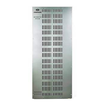
Functional Summary
The CAEN-CK-2x1/4x1/4x2 CAEN Cover Extension
Kits are designed to increase the overall depth of the
CAEN-2x1, CAEN-4x1, and CAEN-4x2 automation
enclosures by 1.5 inches. Adding depth to these
enclosures allows the enclosure to accommodate excess
wiring and third-party devices that may not normally fit in
the standard enclosure.
CAEN-CK Overall Dimensions (Front and Side Views)
HORIZONTAL
PAN (x2)
VERTICAL
BRACKET (x2)
W
The following table lists the dimensions (assembled) for
the CAEN-CK-2x1, CAEN-CK-4x1, and CAEN-CK-4x2.
Dimensions of Enclosure Cover Kits
DIMENSION
CAEN-
CK-2x1
H
23.50 in
D
1.50 in
W
15.35 in
Crestron Electronics, Inc.
15 Volvo Drive Rockleigh, NJ 07647
Tel: 888.CRESTRON
Fax: 201.767.7576
www.crestron.com
D
H
CAEN-
CAEN-
CK-4x1
CK-4x2
38.90 in
38.90 in
1.50 in
1.50 in
15.35 in
26.50 in
CAEN-CK-2x1, 4x1, 4x2
Installation
The cover extension kit should be attached to a Crestron
Automation Enclosure in accordance with all national and
local electrical codes. The enclosure cover and screws
must be removed prior to installation. Both must be
retained and used with the supplied screws to complete
the following procedure.
Refer to the following procedure shown in the installation
diagram when installing the CAEN Cover Extension Kit.
Installation Diagram
1. As shown in the installation diagram, place a
horizontal pan on the bottom and top of the CAEN
enclosure (edges facing inward). Use a #2 Phillips
tip screwdriver to secure the horizontal pans to the
enclosure using the 8-32 screws.
2. As shown in the installation diagram, place a vertical
bracket on the left and right side of the CAEN
enclosure (edges facing outward). Use a #2 Phillips
tip screwdriver and the 8-32 screws to loosely attach
the vertical brackets to the enclosure.
3. Secure the vertical brackets to the secured horizontal
pans with a #2 Phillips tip screwdriver and the 8-32
screws. Tighten the screws holding the vertical
brackets to the CAEN enclosure.
4. After installing the required devices, use the
remaining screws to install the CAEN cover.
Installation Guide – DOC. 6336
®
12.04
Specifications subject to
change without notice.
Advertisement

Related Manuals for Crestron CAEN-CK


Summary of Contents for Crestron CAEN-CK
- Page 1 CAEN-CK-2x1, 4x1, 4x2 Installation The cover extension kit should be attached to a Crestron Automation Enclosure in accordance with all national and local electrical codes. The enclosure cover and screws must be removed prior to installation. Both must be retained and used with the supplied screws to complete the following procedure.
- Page 2 CRESTRON shall not be liable to honor the terms of this warranty if the product has been used in any application other than that for which it was intended, or if it has been subjected to misuse, accidental damage, modification, or improper installation procedures.
Need help?
Do you have a question about the CAEN-CK and is the answer not in the manual?
Questions and answers