
Related Manuals for Crestron C2N-CAMIDSPT


Summary of Contents for Crestron C2N-CAMIDSPT
- Page 1 Crestron C2N-CAMIDSPT Camera Interface, Digital Servo Pan Tilt Head Operations Guide...
- Page 2 This document was prepared and written by the Technical Documentation department at: Crestron Electronics, Inc. 15 Volvo Drive Rockleigh, NJ 07647 1-888-CRESTRON All brand names, product names, and trademarks are the property of their respective owners. ©2005 Crestron Electronics, Inc.
-
Page 3: Table Of Contents
Crestron C2N-CAMIDSPT Contents Camera Interface, Digital Servo Pan Tilt Head: C2N-CAMIDSPT Introduction ... 1 Features and Functions... 1 Specifications ... 4 Physical Description... 5 Industry Compliance ... 10 Setup ... 11 Network Wiring... 11 Identity Code ... 12 Camera/Lens Mounting ... 14 Hardware Hookup ... -
Page 5: Camera Interface, Digital Servo Pan Tilt Head: C2N-Camidspt
(CAMIDSPT) provides fast, smooth, accurate, and silent control of a remote video camera’s pan/tilt position and its lens focus, zoom, and aperture (iris) functions. The CAMIDSPT, designed to work in a Crestron 2-Series control system, employs pulse-width modulation and digital servo technology to attain ultra smooth, ultra fast response with remarkably quiet operation. -
Page 6: Panning And Tilting
In speed mode, the CAMIDSPT responds to signals at the ZOOM RATE, FOCUS RATE, and IRIS RATE analog input joins. In this mode the 2 • Camera Interface, Digital Servo Pan Tilt Head: C2N-CAMIDSPT Crestron C2N-CAMIDSPT... -
Page 7: Personality Modules
Preset Storing and Recalling In conjunction with the Crestron control system, the CAMIDSPT is capable of “memorizing” pan/tilt positions and focus/zoom settings for a virtually unlimited number of presets. Each preset stores a specific position and setting. Presets are supported for motorized lenses that provide zoom and focus positional feedback voltages, and for servomotor lenses operating in position mode. -
Page 8: Specifications
12 lb (5.44 kg) Requires dedicated CNPWS-75 or dedicated channel of C2N-SPWS300, both sold separately. The latest versions can be obtained from the Crestron website. Refer to NOTE below. Crestron 2-Series control systems include the AV2 and PRO2. Consult the latest Crestron Product Catalog for a complete list of 2-Series control systems. -
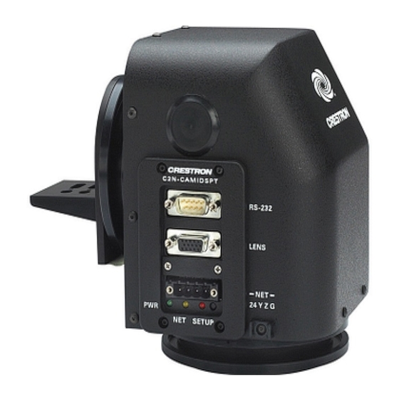
Page 9: Physical Description
All controls and interface connections are located on the side of the unit. Refer to the following illustrations and descriptions. CAMIDSPT Physical View Operations Guide - DOC. 6262A Camera Interface, Digital Servo Pan Tilt Head Camera Interface, Digital Servo Pan Tilt Head: C2N-CAMIDSPT • 5... - Page 10 NOTE: If no personality module is connected, the lens outputs are disabled. Personality Module Options * This is a partial list. Compare your lens motor specs with this Operations Guide to determine compatibility. 6 • Camera Interface, Digital Servo Pan Tilt Head: C2N-CAMIDSPT Bottom 5.52 in (14.02 cm)
-
Page 11: Mounting Plates
Refer to the diagram and pinout table below. To properly wire the mating connector, a wiring schematic for each lens type (A through D) follows the pinout table. Crestron maintains a limited number of cabling drawings for lenses. - Page 12 Camera Interface, Digital Servo Pan Tilt Head Wiring Diagram for Lens A, B, and D (+/-12V, +/-8V, and +/-6V) Wiring Diagram for Lens C (KTS/KTS-A Series and MD/BMD/SD Series) 8 • Camera Interface, Digital Servo Pan Tilt Head: C2N-CAMIDSPT LENS NO CONNECTION...
- Page 13 • Pressing the joystick to the left either pans the camera head to the right or adjusts the lens focus. Camera Interface, Digital Servo Pan Tilt Head: C2N-CAMIDSPT • 9 Pin 1 RS-232 Connector Pin 9...
-
Page 14: Industry Compliance
Mini Joystick Location/Operation Industry Compliance As of the date of manufacture, the C2N-CAMIDSPT has been tested and found to comply with specifications for CE marking and standards per EMC and Radiocommunications Compliance Labelling. NOTE: This device complies with part 15 of the FCC rules. Operation is subject to... -
Page 15: Setup
Cresnet power usage of the entire chain. If the unit is a home-run from a Crestron system power supply network port, the Cresnet power usage of that unit is the Cresnet power usage of the entire run. -
Page 16: Identity Code
Crestron Viewport version 3.35 or later. Use the appropriate method to set the CAMIDSPT Net ID. Method A (Cresnet address-settable ID) 12 • Camera Interface, Digital Servo Pan Tilt Head: C2N-CAMIDSPT Crestron C2N-CAMIDSPT Ensure that the CAMIDSPT is the only device connected to the control system. - Page 17 4. Click on the Search for Touch Settable Devices button. The system searches the network and lists all TSID-enabled devices found. The list is similar to the report produced by pressing F4 (Report Network Devices); Camera Interface, Digital Servo Pan Tilt Head: C2N-CAMIDSPT • 13...
-
Page 18: Camera/Lens Mounting
C2N-CAMI-WMT or C2N-CAMI-CMT, which are available for wall or ceiling mount configurations, respectively. The unit’s operation 14 • Camera Interface, Digital Servo Pan Tilt Head: C2N-CAMIDSPT the first eight digits of each line constitute the TSID number (hexadecimal form of the serial number). - Page 19 Camera Interface, Digital Servo Pan Tilt Head: C2N-CAMIDSPT • 15 0.75 in (1.91 cm) 0.75 in...
- Page 20 Camera Interface, Digital Servo Pan Tilt Head Positioning the Camera/Lens Assembly on the Mounting Plate/Support Bracket Assembly 16 • Camera Interface, Digital Servo Pan Tilt Head: C2N-CAMIDSPT Crestron C2N-CAMIDSPT assembly most closely balances (refer to the following illustration). At this location, reassemble and tighten the mounting screws and washers.
-
Page 21: Hardware Hookup
PERSONALITY BOARDS CRESNET: TO CONTROL SYSTEM AND OTHER CRESNET NET SETUP DEVICES Camera Interface, Digital Servo Pan Tilt Head: C2N-CAMIDSPT • 17 3.0 in (7.62 cm) BHC (bolt hole circle) Adjustable Hard Stops RS-232 LENS: FOR ZOOM, FOCUS, AND IRIS CONTROL... -
Page 22: Power Up Conditions
Replace the cover plate and secure with the two screws removed earlier. The following diagram shows a Cresnet configuration that includes a Crestron TPS touchpanel used to operate the CAMIDSPT. Another typical configuration would include a Crestron Camera Controller such as the CPC-2000A. (A complete configuration for control of a remote video camera would include distribution of the camera’s video output to a local video monitor so you can see the results of your... -
Page 23: Calibration
(home position if no user program is running). The soft stops protect the unit and the camera/lens assembly from jarring during extreme pan and tilt excursions. Camera Interface, Digital Servo Pan Tilt Head: C2N-CAMIDSPT • 19... -
Page 24: Programming Software
Have a question or comment about Crestron software? Answers to frequently asked questions (FAQs) can be viewed in the Online Help section of the Crestron website. To post a question or view questions you have submitted to Crestron’s True Blue Support, log in at http://support.crestron.com/. -
Page 25: C2Net Device Slot In Configuration Manager
System Views. Additional units are assigned different Net ID numbers as they are added. C2Net Device, Slot 9 Operations Guide - DOC. 6262A Camera Interface, Digital Servo Pan Tilt Head Camera Interface, Digital Servo Pan Tilt Head: C2N-CAMIDSPT • 21... -
Page 26: Setting The Net Id In Device Settings
Slot 01: C2N-CAMIDSPT General Controls This slot provides all the controls for normal operation of the CAMIDSPT and attached cameras and lenses. 22 • Camera Interface, Digital Servo Pan Tilt Head: C2N-CAMIDSPT Crestron C2N-CAMIDSPT Operations Guide - DOC. 6262A... - Page 27 Digital output: Indicates that any recalled preset (internal or controller-defined) is <PresetInPos> in the preset position. High/1 = Preset in position; Low/0 = Preset has been moved off position. Camera Interface, Digital Servo Pan Tilt Head: C2N-CAMIDSPT • 23 DESCRIPTION...
- Page 28 Camera Interface, Digital Servo Pan Tilt Head CAMIDSPT General Controls Input and Output Signal Descriptions (continued) (continued on next page) 24 • Camera Interface, Digital Servo Pan Tilt Head: C2N-CAMIDSPT SIGNAL TYPE AND NAME Digital input: Selects speed mode or time mode for the pan/tilt absolute <PT_Spd/Time_Adj>...
- Page 29 <LensTransTime> analog. Valid values range from 1 to 65535. A value of 0 will cause no movement. A command to a specific position will be processed as a preset recall. Camera Interface, Digital Servo Pan Tilt Head: C2N-CAMIDSPT • 25 DESCRIPTION...
- Page 30 Slot 02 Port A: C2N-CAMIDSPT Generic Camera Controls This port serves as an RS-232 port for two-way communication with serial devices. CAMIDSPT RS-232 Port A Generic Camera for C2N-CAMIDSPT Input and Output Signals 26 • Camera Interface, Digital Servo Pan Tilt Head: C2N-CAMIDSPT...
- Page 31 The C2N-CAMIDSPT RS-232 port is capable of receiving complex serial data in the form of serial data strings on this input line. str2 The C2N-CAMIDSPT RS-232 port is capable of sending complex serial data in the form of serial data strings on this output line. delimiter When present, the delimiter is appended to every string of text in the port definition (both transmitted and received strings).
-
Page 32: Uploading And Upgrading
Camera Interface, Digital Servo Pan Tilt Head Uploading and Upgrading NOTE: Crestron recommends that you use the latest software and that each device contains the latest firmware to take advantage of the most recently released features. Please check the Crestron website (http://www.crestron.com/updates) for the latest versions of software and firmware. - Page 33 “Port Settings” window are selected as shown on the next page. Click the OK button to save the settings and close the window. Camera Interface, Digital Servo Pan Tilt Head: C2N-CAMIDSPT • 29...
-
Page 34: Uploading A Simpl Windows Program
.spz for a 2-Series control system. Upload via Crestron Viewport 30 • Camera Interface, Digital Servo Pan Tilt Head: C2N-CAMIDSPT Crestron C2N-CAMIDSPT 4. To verify communication, select Diagnostics | Establish Communications (Find Rack). This should display a window that gives the COM port and baud rate. -
Page 35: Firmware Upgrade
A firmware upgrade file has To take advantage of all the CAMIDSPT features, it is important that the unit contains the latest firmware available. Please check the Crestron website for the latest the extension .upg. version of firmware. Not every product has a firmware upgrade, but as Crestron improves functions, adds new features, and extends the capabilities of its products, firmware upgrades are posted. - Page 36 38400 to match the Cresnet bus speed. “Open” Window 32 • Camera Interface, Digital Servo Pan Tilt Head: C2N-CAMIDSPT Crestron C2N-CAMIDSPT 3. As shown after this step, select the Net ID of the CAMIDSPT and then click OK.
-
Page 37: Problem Solving
Requires dedicated CNPWS-75 or dedicated channel of C2N-SPWS300, both sold separately. Camera Interface, Digital Servo Pan Tilt Head: C2N-CAMIDSPT • 33 CORRECTIVE ACTION Use a Crestron power supply.* Verify that cables plugged into NET port are secure. -
Page 38: Further Inquiries
For assistance in your local time zone, refer to the Crestron website (http://www.crestron.com/) for a listing of Crestron worldwide offices. You can also log onto the online help section of the Crestron website to ask questions about Crestron products. First-time users will need to establish a user account to fully benefit from all available features. -
Page 39: Return And Warranty Policies
CRESTRON shall not be liable to honor the terms of this warranty if the product has been used in any application other than that for which it was intended, or if it has been subjected to misuse, accidental damage, modification, or improper installation procedures. - Page 40 Crestron Electronics, Inc. Operations Guide – DOC. 6262A 15 Volvo Drive Rockleigh, NJ 07647 (2010201) Tel: 888.CRESTRON 03.05 Fax: 201.767.7576 Specifications subject to www.crestron.com change without notice.
Need help?
Do you have a question about the C2N-CAMIDSPT and is the answer not in the manual?
Questions and answers