Table of Contents
Advertisement
Quick Links
Operation/Repair/Parts
GS950 Airless Sprayers
For professional use only.
Not approved for use in European explosive atmosphere locations.
For the application of architectural paints and coatings.
3300 psi (22.7 MPa, 227 bar) Maximum Working Pressure
Important Safety Instructions
Read all warnings and instructions in this manual and in related manuals.
Be familiar with the controls and the proper usage of the equipment.
Save these instructions.
Related Manuals:
3A4133
Gun
3A4347
Pump
3A4108F
EN
ti29064a
Advertisement
Table of Contents

Subscribe to Our Youtube Channel
Related Manuals for AIRLESSCO GS950


Summary of Contents for AIRLESSCO GS950
- Page 1 Operation/Repair/Parts 3A4108F GS950 Airless Sprayers For professional use only. Not approved for use in European explosive atmosphere locations. For the application of architectural paints and coatings. 3300 psi (22.7 MPa, 227 bar) Maximum Working Pressure Important Safety Instructions Read all warnings and instructions in this manual and in related manuals.
-
Page 2: Table Of Contents
Parts List - GS950 ........29... -
Page 3: Warnings
Warnings Warnings The following warnings are for the setup, use, grounding, maintenance, and repair of this equipment. The exclamation point symbol alerts you to a general warning and the hazard symbols refer to procedure-specific risks. When these symbols appear in the body of this manual or on warning labels, refer back to these Warnings. - Page 4 Check hoses and parts for signs of damage. Replace any damaged hoses or parts. • This system is capable of producing 3300 psi. Use Airlessco replacement parts or accessories that are rated a minimum of 3300 psi. • Always engage the trigger lock when not spraying. Verify the trigger lock is functioning properly.
- Page 5 Warnings EQUIPMENT MISUSE HAZARD Misuse can cause death or serious injury. • Do not operate the unit when fatigued or under the influence of drugs or alcohol. • Do not exceed the maximum working pressure or temperature rating of the lowest rated system component.
- Page 6 Warnings TOXIC FLUID OR FUMES HAZARD Toxic fluids or fumes can cause serious injury or death if splashed in the eyes or on skin, inhaled, or swallowed. • Read Safety Dara Sheet (SDS) to know the specific hazards of the fluids you are using.
-
Page 7: Component Identification
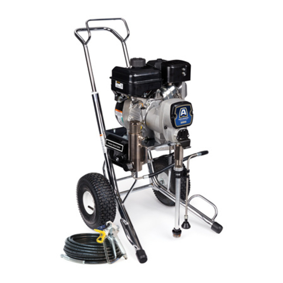
Component Identification Component Identification Standard Models (GS950) ti29071a Engine ON/OFF Switch Grounding Clamp Pump On/Off Switch Pressure Control Prime Valve Gun Trigger Lock Strainer Pump Engine Controls Drain Hose Easy Out Pump Filter 3A4108F Hose... -
Page 8: Pressure Relief Procedure
Pressure Relief Procedure Pressure Relief Procedure Grounding Follow the Pressure Relief Procedure whenever you see this symbol. This equipment must be grounded to reduce the risk of static sparking. Static sparking can cause fumes to ignite or explode. Grounding provides an escape wire for the electric current. -
Page 9: Setup
Setup Setup Fill throat packing nut with TSO to prevent premature packing wear. Do this each time you spray. Connect appropriate high-pressure hose to sprayer. Connect hose to fluid inlet of spray gun ti29075a and tighten securely. Check engine oil level. Add 5W-30 synthetic, if necessary. -
Page 10: Startup
Startup Startup Start Engine Move fuel valve to open. Place suction tube and drain tube in ti29097a grounded metal pail partially filled with Move choke to closed. flushing fluid. Attach ground wire to pail and to earth ground. ti29098a Set throttle to fast. ti29079a Turn prime valve down to DRAIN position. - Page 11 Startup Set throttle to 50% setting to prime 12. Hold gun against grounded metal sprayer. flushing pail. Trigger gun and increase fluid pressure slowly until pump runs smoothly. ti29211c Turn pump switch to ON position. ti29103a Inspect fittings for leaks. Do not stop leaks with your hand or a rag! If leaks occur, turn sprayer OFF immediately.
-
Page 12: Tip Guard Assembly
Tip Guard Assembly Tip Guard Assembly Insert tip. Perform Pressure Relief Procedure, page 8. Engage gun trigger lock. Insert seat and seal using end of finger hold. ti29115a Screw assembly onto gun. Tighten. ti29114a ti29116a 3A4108F... -
Page 13: Spray
Spray Spray Clearing Tip Clogs Spray test pattern. Increase pressure to eliminate heavy edges. Use smaller tip size if pressure adjustment can not To avoid serious injury, never point gun at eliminate heavy edges. your hand or into a rag. Release trigger, engage trigger lock. -
Page 14: Cleanup
Cleanup Cleanup Set throttle to fast. Perform Pressure Relief Procedure, steps 1 - 4. Remove siphon tube set from ti29098b paint and place in flushing fluid. Remove tip guard from gun. Set engine switch to ON. ti29099a Pull rope to start engine. ti29079a NOTE: Use water for water-base paint, mineral spirits for oil-base paint, or other... - Page 15 Cleanup Increase pressure to 1/2. Hold gun 10. Turn prime valve down DRAIN position. against paint pail. Disengage trigger lock. Trigger gun until flushing fluid appears. ti29132a ti29128a 11. Remove filters from gun and sprayer, if Move gun to waste pail, hold gun against installed.
-
Page 16: Maintenance
Maintenance Maintenance WEEKLY: Remove engine air filter cover and clean element. Replace element, if necessary. If operating in an unusually dusty environment: check filter daily and replace, if necessary. Replacement elements can be purchased from your local Briggs & Stratton dealer. AFTER EACH 50 HOURS OF NOTE: For detailed engine maintenance and OPERATION:... -
Page 17: Troubleshooting
Troubleshooting Troubleshooting PROBLEM CAUSE SOLUTION Engine will not start Engine switch is OFF. Turn engine switch ON. Engine is out of gasoline. Refill gas tank. Engine oil level is low. Try to start engine. Replenish oil, if necessary. Spark plug disconnected or Connect spark plug cable or damaged. - Page 18 Troubleshooting PROBLEM CAUSE SOLUTION Engine operates, but Pump switch is OFF. Turn pump switch ON. displacement pump does Pressure setting too low. Turn pressure adjusting knob not operate. clockwise to increase pressure. Fluid filter is dirty. Clean filter. Tip or tip filter is clogged. Clean tip or tip filter (see gun manual).
- Page 19 Troubleshooting PROBLEM CAUSE SOLUTION Pump output is low Strainer is clogged. Clean strainer. Piston ball is not seating. Service piston ball (see pump manual). Piston packings are worn or Replace packings (see pump damaged. manual). O-ring in pump is worn or damaged. Replace o-ring (see pump manual).
- Page 20 Troubleshooting PROBLEM CAUSE SOLUTION Pump is difficult to prime Air in pump or hose. Check and tighten all fluid connections. Reduce engine speed and cycle pump as slowly as possible during priming. Intake valve is leaking. Clean intake valve. Be sure ball seat is not nicked or worn and that ball seats well.
-
Page 21: Fluid Pump Runs Constantly
Fluid Pump Runs Constantly Fluid Pump Runs Constantly Perform Pressure Relief Procedure, page 8, turn prime valve forward to SPRAY position, and turn power switch OFF. Remove control box cover. Troubleshooting Procedure: With a pressure gauge plumbed into Pump problem. See the proper fluid the paint hose, start the engine. -
Page 22: Control Board Malfunction
Control Board Malfunction Control Board Malfunction Troubleshooting Procedure (see following page for actual steps): Remove control box cover. Turn sprayer ON. Observe control board Green and Red LED Lights. Go to step 1. Replace the No light Does switch switch. Normal Operation test positive? Once... -
Page 23: Error Code Section
Exceeded pressure limit. Check fluid path for clogs, such as clogged filter. BLINKS is running. Use Airlessco paint hose, 1/4 in. x 50 ft minimum. 2 TIMES Smaller hose or metal braid hose may result in pressure spikes. Replace transducer if fluid path is not clogged and proper hose is used. -
Page 24: Control Board Malfunction (Steps)
Control Board Malfunction (Steps) Control Board Malfunction (Steps) STEP 3. STEP 2. STEP 1. 10-12 DC Leave engine Turn engine Turn 12 -20 AC BEEP running and ON. Set engine turn switch meter to AC OFF and ON. Turn volts and set meter potentiometer connect wires... -
Page 25: Pinion Assembly/Clutch Armature/Clamp
Pinion Assembly/Clutch Armature/Clamp Pinion Assembly/Clutch Armature/Clamp Pinion Assembly/Clutch Remove four screws (28) and lock washers (24). Install two screws in Armature Removal threaded holes (E) in rotor. Alternately tighten screws until rotor comes off. Pinion Assembly If pinion assembly (29) is not removed from clutch housing (19), do 1. -
Page 26: Installation
Pinion Assembly/Clutch Armature/Clamp Clutch Armature Pinion Assembly Check o-ring (29d) and replace if Use an impact wrench or wedge missing or damaged. something between clutch armature (25) and clutch housing to hold engine shaft Tap pinion shaft (29a) in with plastic during removal. -
Page 27: Clamp Removal
Pinion Assembly/Clutch Armature/Clamp Clamp Removal Drain gasoline from tank according to Briggs & Stratton manual. Tip engine on side so gas tank is down and air cleaner is up. Loosen two screws (24) on clamp (22). Remove engine. Push screwdriver into slot in clamp (22) and remove clamp. -
Page 28: Parts Drawing - Gs950
Parts Drawing - GS950 Parts Drawing - GS950 Part Specifications: Ref. Instruction Ref. Instruction Inflate tires to 28-32 psi (1.93-2.21 Torque to 115-135 in-lb (12.9-15.2 N•m) bar/0.193-0.221 MPa) Torque to 70-80 ft-lb (94.9-108.4 N•m) Torque to 25-35 in-lb (2.8-3.9 N•m) Torque to 130-150 in-lb (14.6-16.9 N•m) -
Page 29: Parts List - Gs950
Parts List - GS950 Parts List - GS950 Ref. Part Description Ref. Part Description 107434 BEARING, thrust 25P374 ENGINE, gasoline, 6.5 HP 100214 WASHER, lock 110837 SCREW, flange, hex 108842 SCREW, cap, hex hd 110838 NUT, lock 119420 WHEEL, pneumatic... -
Page 30: Control Box 25P548
Control Box 25P548 Control Box 25P548 ti29342a Ref. Part Description Ref. Part Description 116585 SCREW, pan, X recess, sst 25P548 CONTROL BOX 113160 SCREW, mach, slot, hex 70a 17M317 BOX wash hd 70b 25P550 KIT, repair, control board 15C973 GASKET 70c 117317 SCREW, plastite, pan head 120 16Y415 GASKET, transducer... -
Page 31: Filter (Gs950)
Filter (GS950) Filter (GS950) Part Specifications: Ref. Part Description 243222 TRANSDUCER, pressure Ref. Instruction control, includes 63 224807 BASE, valve Torque to 130-150 in-lb (14.6-16.9 N•m) 235014 VALVE, drain, includes 22a, Torque to 35-45 ft-lb (47.4-61.0 N•m) 15C780 HANDLE, Torque to 90-110 in-lb (10.1-12.4 N•m) -
Page 32: Pressure Control Wiring Diagrams
Pressure Control Wiring Diagrams Pressure Control Wiring Diagrams GS950 DRIVE HOUSING PINON HOUSING TO GROUND CLUTCH B CLUTCH A TO ENGINE CONTROL BOARD ON/OFF SWITCH TRANSDUCER POTENTIOMETER 3A4108F... -
Page 33: Technical Data
Technical Data Technical Data GS950 Metric Engine Vanguard 5.5 Hp (205 cc) Power Rating @ 3400 RPM 5.5 Hp 4.1 KW Sprayer Maximum Working Pressure 3300 psi 227 bar, 22.7 MPa Maximum Delivery Rating 0.75 gpm 2.84 lpm 12 mesh (1523 micron) - Page 34 Notes Notes 3A4108F...
-
Page 35: Airlessco Standard Warranty
With the exception of any special, extended, or limited warranty published by Airlessco, Airlessco will, for a period of twelve months from the date of sale, repair or replace any part of the equipment determined by Airlessco to be defective. This warranty applies only when the equipment is installed, operated and maintained in accordance with Airlessco’s written recommendations. - Page 36 All written and visual data contained in this document reflects the latest product information available at the time of publication. Airlessco reserves the right to make changes at any time without notice. Original Instructions. This manual contains English. MM 3A4108 GRACO INC.
Need help?
Do you have a question about the GS950 and is the answer not in the manual?
Questions and answers