Table of Contents
Advertisement
Quick Links
Getting started with the X-NUCLEO-DRP1M1 USB Type-C™ Power Delivery
dual role port expansion board based on TCPP03-M20 for STM32 Nucleo
Introduction
The
X-NUCLEO-DRP1M1
expansion board allows evaluating the features of
protections required for V
BUS
The expansion board can be stacked on top of any STM32 Nucleo-64 with Power Delivery (UCPD) peripheral embedded in their
microcontrollers.
The
X-NUCLEO-DRP1M1
effectively demonstrates the dead battery and Sink operation, thanks to the integrated
LDO linear regulator that supplies the connected
Source operation when a compatible external Source is connected to the board.
Moreover, the expansion board allows Dual Role Data functionalities for sourcing devices.
The
X-NUCLEO-DRP1M1
is compliant with the USB Type-C™ and Power Delivery specifications 3.1 standard power range
(SPR) and is USB-IF certified as a 100 W DRP solution supporting programmable power supply (PPS).
The companion software package (X-CUBE-TCPP) contains the application examples for development boards embedding
UCPD-based microcontrollers (NUCLEO-G071RB,
UM2891 - Rev 1 - June 2021
For further information contact your local STMicroelectronics sales office.
and CC lines suitable for dual role power (DRP) applications.
STM32 Nucleo
NUCLEO-G474RE
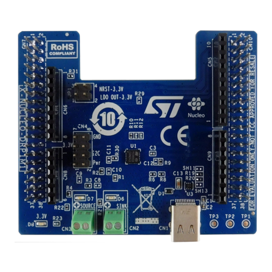
Figure 1.
X-NUCLEO-DRP1M1 expansion board
TCPP03-M20
and the USB Type-C™ features and
development board. It also demonstrates USB Type-C™
and NUCLEO-G0B1RE).
UM2891
User manual
ST715PU33R
www.st.com
Advertisement
Table of Contents

Subscribe to Our Youtube Channel
Related Manuals for ST X-NUCLEO-DRP1M1


Summary of Contents for ST X-NUCLEO-DRP1M1
-
Page 1: Figure 1. X-Nucleo-Drp1M1 Expansion Board
UM2891 User manual Getting started with the X-NUCLEO-DRP1M1 USB Type-C™ Power Delivery dual role port expansion board based on TCPP03-M20 for STM32 Nucleo Introduction X-NUCLEO-DRP1M1 expansion board allows evaluating the features of TCPP03-M20 and the USB Type-C™ features and protections required for V and CC lines suitable for dual role power (DRP) applications. -
Page 2: Getting Started
UM2891 Getting started Getting started Overview X-NUCLEO-DRP1M1 expansion board features: • Support for all USB Type-C™ Power Delivery SPR profiles up to 100 W • Management of Dual Role Data/Power configuration • USB 2.0 Dual Role Data compliant according to STM32 USB data capability •... -
Page 3: Hardware Architecture
STM32 Nucleo-64 development board embedding the UCPD peripheral (mainly NUCLEO-G071RB, NUCLEO-G474RE and NUCLEO-G0B1RE). The expansion board must be plugged on the matching pins of the development board CN7 and CN10 ST morpho connectors. When plugged onto an STM32 Nucleo... -
Page 4: Figure 3. X-Nucleo-Drp1M1 Main Functional Blocks (Top View)
UM2891 Hardware architecture Figure 3. X-NUCLEO-DRP1M1 main functional blocks (top view) 1-2. Morpho connectors 3-6. Arduino connectors 7. Type-C™ connector 8. Provider path screw connector plus LED 9. Consumer path screw connector plus LED 10. 3.3 V LED 11. Jumpers for self-powering (LDO out plus NRST) -
Page 5: Type-C™ Connector
UM2891 Type-C™ connector Figure 4. X-NUCLEO-DRP1M1 main functional blocks (bottom view) Morpho connector Morpho connector OVP threshold solder bridges (R0, SH2, SH3, SH4, SH5) ST715PU33R high input voltage LDO linear regulator (U2) STL40DN3LLH5 dual N-channel 30 V, 0.016 Ohm, 11 A STripFET H5 Power MOSFET (Q1 and Q2) Current sense shunt resistor Type-C™... -
Page 6: Usb 2.0 Data Path And Configuration Settings
STM32 Nucleo development boards that feature a USB2.0 peripheral to expose the D+/D- lines on the Type-C™ receptacle (CN1). Most STM32 Nucleo-64 development boards feature this functionality on the ST morpho connector CN10-12 and CN10-14 pins, whereas NUCLEO-L412RB-P, NUCLEO-L433RC-P, NUCLEO-L452RE-P NUCLEO-L476RG boards map USB2.0 data pins on CN10-33 and CN10-17 pins. -
Page 7: St Morpho And Arduino V3 Connectors
CC2_G4 CC2_G4 SSQ-106-03-G-S SSQ-108-03-F-S CC lines are connected to the UCPD connection of the ST morpho connectors (CN7, CN10). Two configurations are possible according to the ST morpho connectors on the STM32 Nucleo development board. To limit pin count on the STM32, unused lines can be disconnected by removing R26/R25 or R24/R27. -
Page 8: C Bus
R28; level high is then connected to TCPP03-M20 I2C_ADD pin. C pull-up 1 kΩ resistors (R11 and R12) are present on the X-NUCLEO-DRP1M1. Voltage/current analog sense connection to STM32 ADC X-NUCLEO-DRP1M1 features three voltage senses connected to the STM32 ADC: •... -
Page 9: Figure 9. Consumer And Provider Path
UM2891 Consumer and provider path Figure 9. Consumer and provider path STL40DN3LLH5 SINK 200k 1725656 STL40DN3LLH5 ADC_Cons 40.2k STL40DN3LLH5 SOURCE 200k 1725656 STL40DN3LLH5 ADC_Prov FLGN 40.2k ISENSE VBUSc 3.3V VSENSE FLGn VCC / VCONN CBIAS CC1c CC1c CC2c CC2c IANA ENABLE I2C_ADD TCPP03-M20... -
Page 10: Vbus And Cc Lines Over-Current Protection
, OVP turns on, the consumer and provider paths are opened and register 2 is updated. On the X-NUCLEO-DRP1M1 expansion board, the resistor connected to V (R6) is set to 10 kΩ. OVP threshold can be adjusted thanks to the resistor connected to GND. R13 to R17 resistors can be selected with R0, SH2, SH3, SH4 and SH5. -
Page 11: Ldo
1 – 2 to connect 3.3 V output voltage to the system 3.3 V • jumper between 3 – 4 to force STM32 NRST pin to 3.3 V (otherwise it would be HZ with potential parasitic reset) D8 LED signals the 3.3 V presence on X-NUCLEO-DRP1M1. UM2891 - Rev 1 page 11/27... -
Page 12: Tcpp03-M20
UM2891 TCPP03-M20 Figure 11. LDO configuration SINK High input voltage 3.3V BAT54KFILM 85 mA LDO linear regulator ST715PU33R LED red Consumer NRST TSW-102-07-F-D 100n 25V 470n 5V Exp Pad GND SOURCE LED green BAT54KFILM 3. 3 V LED blue Provider 1.12 TCPP03-M20 3.3 V is connected to... -
Page 13: Stm32 Resources
Other resources are: • USB 2.0 peripheral • ADC to get consumer and provider path voltages as well as current on V images Table 2. X-NUCLEO-DRP1M1 - STM32 resources USB-PD low USB-PD minimal Additional STM32 resource power X-NUCLEO-DRP1M1 associated connection... -
Page 14: Demo Application Setup
ST-LINK is connected These two modes cannot be merged as the STM32 NRST pin is managed by 3.3 V coming from ST-LINK. If ST-LINK is not powered, STM32 NRST pin becomes HZ and might generate parasitic resets. -
Page 15: Programming/Debugging Example For Stm32G474Re
3.3 V LED on, Source LED off, Sink LED on STM33G474RE system validation 3.3.1 Hardware configuration Step 1. On the X-NUCLEO-DRP1M1, add two jumpers on JP1: LDO OUT 3.3 V and NRS 3.3 V to power STM32G474RE with 3.3 V LDO output. Step 2. -
Page 16: Applicative Use Cases
UM2891 STM33G474RE system validation 3.3.3 Applicative use cases Battery working (5 V source connected on the Source connector) and Sink device connected to the Type- C™ connector: – Sink device can be a smartphone, USB key, hardware drive, accessory, etc. –... -
Page 17: Schematic Diagrams
Schematic diagrams Figure 14. X-NUCLEO-DRP1M1 schematic diagram (1 of 3) VBUS STL40DN3LLH5 SINK ConUSB31_632723300011_recept 200k 1725656 STL40DN3LLH5 ADC_Cons GND6 GND3 SSRXp1 SSTXp1 SSRXn1 SSTXn1 40.2k VBUS4 VBUS1 CC1c SBU2 0.007 CC2c STL40DN3LLH5 SBU1 SOURCE VBUS3 VBUS2 SSTXn2 SSRXn2 200k SSTXp2... -
Page 18: Figure 15. X-Nucleo-Drp1M1 Schematic Diagram (2 Of 3)
Figure 15. X-NUCLEO-DRP1M1 schematic diagram (2 of 3) 3.3V CN10 SSQ-108-03-F-S SSQ-110-03-F-S ENABLE I2C1_SCL I2C1_SDA NRST CC1_G4 ADC_Vbusc CC2_G0 ADC_Prov ADC_Cons CC1_G0 ADC_Isense DP_other FLGN ESQ-119-14-T-D ESQ-119-14-T-D R27 0 CC2_G4 SSQ-106-03-G-S SSQ-108-03-F-S SH17 3.3V SH16 SOURCE I2C1_SCL I2C1_SDA I2C_ADD 3.3V... -
Page 19: Figure 16. X-Nucleo-Drp1M1 Schematic Diagram (3 Of 3)
Figure 16. X-NUCLEO-DRP1M1 schematic diagram (3 of 3) SINK 3.3V High input voltage BAT54KFILM 85 mA LDO linear regulator ST715PU33R LED red Consumer NRST TSW-102-07-F-D 100n 25V 470n 5V Exp Pad GND SOURCE LED green BAT54KFILM 3. 3 V LED blue... -
Page 20: Bill Of Materials
UM2891 Bill of materials Bill of materials Table 3. X-NUCLEO-DRP1M1 bill of materials Item Q.ty Ref. Part/Value Description Manufacturer Order code TCPP03-M20, Type-C™ Port TCPP03-M20 QFN20 4.0x4.0 Protection DRP Common mode ECMF02-2AMX6, filter with ESD ECMF02-2AMX6 DFN6 1.7x1.5 protection ESDA25P35-1U1 M, DFN 1.6x1.0,... - Page 21 UM2891 Bill of materials Item Q.ty Ref. Part/Value Description Manufacturer Order code 5470nF, 0402, 5 MLCC 0402 X5C Wurth 885012105004 V, ±1% 6VDC Electronics Inc. 0.007, 1206, ±1% Resistor Panasonic ERJMP2MF7M0U 200 k, 0402, 1/16 R1, R3, R8 Resistors W, ±1% 40.2 k, 0402, 1/16 R2, R4, R9 Resistors...
-
Page 22: Revision History
UM2891 Revision history Table 4. Document revision history Date Revision Changes 28-Jun-2021 Initial release. UM2891 - Rev 1 page 22/27... -
Page 23: Table Of Contents
ST morpho and Arduino V3 connectors ........ - Page 24 UM2891 Contents List of figures................26 UM2891 - Rev 1 page 24/27...
-
Page 25: List Of Tables
X-NUCLEO-DRP1M1 - STM32 resources ........ - Page 26 X-NUCLEO-DRP1M1 main functional blocks (bottom view) ........
- Page 27 ST’s terms and conditions of sale in place at the time of order acknowledgement. Purchasers are solely responsible for the choice, selection, and use of ST products and ST assumes no liability for application assistance or the design of Purchasers’...
Need help?
Do you have a question about the X-NUCLEO-DRP1M1 and is the answer not in the manual?
Questions and answers