Table of Contents
Advertisement
Quick Links
Advertisement
Table of Contents

Related Manuals for Global American 3301260

Summary of Contents for Global American 3301260
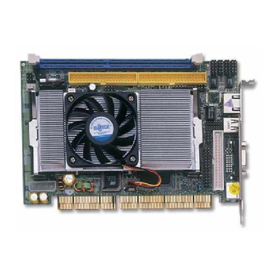
- Page 1 3301260/3304000 ® ® Pentium M/ Celeron PCI-ISA Bus Industrial Single Board Computer •CompactFlash•DDR• •DVI-I/CRT/LVDS Panel•LAN•Audio• ATA/33/66/100•RS-232/422/485• •4 COM•USB2.0•WDT•H/W Monitor• •PCI-ISA Bus Industrial Single Board computer•...
- Page 2 Copyright Disclaimers The accuracy of contents in this manual has passed thorough checking and review before publishing. Global American Inc., the manufacturer and publisher, is not liable for any infringements of patents or other rights resulting from its use. The...
-
Page 3: Table Of Contents
Table of Contents Chapter 1 General Description ........1 Major Features ............. 2 Specifications .............. 3 Board Dimensions ............4 Chapter 2 Unpacking ..........5 Opening the Delivery Package ........5 Inspection..............5 Chapter 3 Hardware Installation ......7 Before Installation ............7 Board Layout ............... - Page 4 Chapter 4 Award BIOS Setup .........23 Starting Setup ............23 Using Setup..............24 Main Menu ..............25 Standard CMOS Features ......... 26 Advanced BIOS Features ......... 27 Advanced Chipset Features ........28 Integrated Peripherals..........29 Power Management Setup........31 PnP/PCI Configurations ..........32 4.10 PC Health Status............
- Page 5 Fasten the ALLIGATOR clip of the strap to the end of the shielded wire lead from a grounded object. Please wear and connect the strap before handling the 3301260 to protect yourself from the discharge of any static electricity through the strap.
-
Page 6: General Description
DVI-I/CRT/LVDS Panel, LAN, audio, 4 COM and USB2.0 port interface. Its onboard ATA/33/66/100 connected to IDE drive interface architecture allows the 3301260/3304000 to support data transfers of 33, 66 or 100MB/sec. for each IDE drive connection. Designed with ® the Intel 82852GM/82801DB core logic chipset, the board supports all ®... -
Page 7: Major Features
Additional onboard connectors include two internal and one external USB2.0 connectors providing faster data transmission, and one external RJ-45 connector for use of one 10/100 Base-TX Ethernet interfaces. Major Features 3301260 3304000... -
Page 8: Specifications
The 3301260/3304000 comes with the following features: ® ® ¾ 3301260 provides PGA 479 for Intel Pentium M 1.2~1.7GHz CPU ® ® 3304000 provides Intel Mobile Celeron M 600MHz low power embedded CPU ¾ One DDR socket with a max. capacity of 1GB ®... -
Page 9: Board Dimensions
„ Watchdog Timer: Software programmable time-out intervals from 1~256 sec. „ CMOS: Battery backup „ Power Connector: One 4-pin power connector „ Temperature: 0~+60°C (operating); -20~+80°C (storage) „ Hardware Monitor: Winbond W83627HF „ Board Size: 18.6(L) x 12.2(W) cm Board Dimensions... -
Page 10: Unpacking
Chapter 2 Unpacking Opening the Delivery Package The 3301260/3304000 is packed in an anti-static bag. The board has components that are easily damaged by static electricity. Do not remove the anti-static wrapping until proper precautions have been taken. Safety Instructions in front of this manual describe anti-static precautions and procedures. - Page 11 Cables Package Description Two USB flat cable with bracket x 1 ATA/100 IDE flat cable x 2 Floppy flat cable x 1 Parallel port flat cable with bracket x 1 Two COM flat cable with bracket x 2 MIC/Audio flat cable x 1 Keyboard/Mouse transfer cable x 1 If you want to use DVI-I device under WIN98 or WINNT, please purchase this cable separately.
-
Page 12: Hardware Installation
NOTE: Since AD22 has been assigned for ISA bridge at 3301260/3304000, please make sure do not use this address for other PCI cards to avoid confliction. In order to get detailed information, please contact technical support engineer. -
Page 13: Board Layout
Board Layout... -
Page 14: Jumper List
Jumper List Jumper Default Setting Setting Page COM 2 Use RS-232 or RS-422/485 Select: RS-232 Open Clear CMOS: Normal Operation 1-2 Short Connector List Connector Definition Page Reset Connector HDD LED Connector Power LED Connector MIC In/Audio Out Connector CN6 / CN7 / CN8 / CN10 COM 1~COM 4 Connector (5x2 header) DVI-I Connector CN11... -
Page 15: Configuring The Cpu
Please smear the heat sink paste over CPU and 82852GM uniformly. Then secure the heat sink as the picture above System Memory The 3301260/3304000 provides one DDR socket at location DM1. The maximum capacity of the onboard memory is 1GB. -
Page 16: Vga Controller
VGA Controller The onboard Intel 82852GM supports DVI-I/CRT/LVDS Panel display up to 1600 x 1200. The 3301260/3304000 provides three methods of connecting VGA device. CN12 offers a single standard CRT connector (DB15), or CN9 offers DVI-I connector, or Panel2/Panel1 offer 24-bit/48-bit LVDS panel connectors. - Page 17 z J2: Inverter Power In Connector Description +12V +12V BackLight Enabled LCD Enabled z Panel2: 24-bit LVDS Panel Connector PIN Description PIN Description VCC3 VCC3 CLKBM CLKBP z Panel1: 24-bit LVDS Panel Connector PIN Description PIN Description VCC3 VCC3 CLKAM CLKAP NOTE: If using Panel2/Panel1 only, it just supports 24-bit LVDS Panel;...
-
Page 18: Pci E-Ide Drive Connector
IDE2 and IDE1 are standard 40-pin daisy-chain driver connector that serves E-IDE drive provisions onboard 3301260/3304000. A maximum of four ATA/33/66/100 IDE drives can be connected to the 3301260/3304000 via IDE1 and IDE2. z IDE2: Primary IDE Connector Description Description RESET PDATA 7 PDATA 8... - Page 19 IDE1: Secondary IDE Connector Description Description RESET SDATA 7 SDATA 8 SDATA 6 SDATA 9 SDATA 5 SDATA 10 SDATA 4 SDATA 11 SDATA 3 SDATA 12 SDATA 2 SDATA 13 SDATA 1 SDATA 14 SDATA 0 SDATA 15 SDREQ SIOW# SIOR# SIORDY...
-
Page 20: Floppy Disk Drive Connector
Floppy Disk Drive Connector The 3301260/3304000 uses a standard 34-pin header connector, FD1, for floppy disk drive connection. A total of two FDD drives may be connected to FD1 at any given time. z FD1: FDD Connector Description Description DRVDEN0... -
Page 21: Serial Port Connectors
3.10 Serial Port Connectors The 3301260/3304000 offers two NS16C550 compatible UARTs with Read/Receive 16-byte FIFO serial ports and four internal 10-pin headers. z CN6~8/CN10: COM1~COM4 Connector (5x2 header) PIN Description PIN Description 2 DSR RXD 3 4 RTX 6 CTX... -
Page 22: Parallel Connector
3.11 Parallel Connector LP1 is a standard 26-pin flat cable connector designed to accommodate parallel port connection onboard 3301260/3304000. z LP1: Parallel Connector PIN Description PIN Description Strobe Auto Form Feed DATA 0 ERROR# DATA 1 Initialize DATA 2 Printer Select LN#... -
Page 23: Ethernet Connector
BD0+ BD1+ z US2: External USB2.0 Connector PIN Description PIN Description BD0- BD0+ 3.14 CMOS Data Clear The 3301260/3304000 has a Clear CMOS jumper on JP2. z JP2: Clear CMOS Options Settings Normal Operation (default) Short 1-2 Clear CMOS Short 2-3... -
Page 24: Power And Fan Connectors
3.15 Power and Fan Connectors 3301260/3304000 provides one 4-pin power in connector at PW1. z PW1: 4-pin Power In Connector PIN Description +12V FN1 and FN2 onboard 3301260/3304000 are 3-pin fan power connectors. z FN1: Fan Power Connector Description +12V... -
Page 25: System Front Panel Connectors
3.17 System Front Panel Connectors The 3301260/3304000 has one LED at location CN3 that indicates the system front panel status. This visual feature of the HDD LED may also be connected to an external HDD LED via connector CN8. At location CN1 is Reset button connector. -
Page 26: Audio Connectors
User can also use AL, 00H’s defined time for reset purposes, e.g.00H for Disable, 01H = 1sec, 02H = 2sec to FFH = 255sec. 3.19 Audio Connectors The 3301260/3304000 has an onboard AC97 3D audio interface. The following tables list the pin assignments of the MIC In/Line Out connectors. -
Page 27: Compactflash Connector
3.20 CompactFlash Connector The 3301260/3304000 also offers an optional CompactFlash connector which is IDE interface located at the solder side of the board. The designated CN13 connector, once soldered with an adapter, can hold CompactFlash cards of various sizes. Please turn off the power before inserting the CF card. -
Page 28: Award Bios Setup
Chapter 4 Award BIOS Setup The 3301260/3304000 uses Award BIOS for the system configuration. The Award BIOS setup program is designed to provide the maximum flexibility in configuring the system by offering various options that could be selected for end-user requirements. This chapter is written to assist you in the proper usage of these features. -
Page 29: Using Setup
Using Setup In general, you use the arrow keys to highlight items, press <Enter> to select, use the <PageUp> and <PageDown> keys to change entries, press <F1> for help and press <Esc> to quit. The following table provides more detail about how to navigate the Setup program using the keyboard. -
Page 30: Main Menu
Main Menu Once you enter the Award BIOS CMOS Setup Utility, the Main Menu will appear on the screen. The Main Menu allows you to select from several setup functions and two exit choices. Use the arrow keys to select among the items and press <Enter> to enter the sub-menu. Phoenix AwardBIOS CMOS Setup Utility ` Standard CMOS Features... -
Page 31: Standard Cmos Features
Standard CMOS Features The Standard Setup is used for the basic hardware system configuration. The main function is for Data/Time and Floppy/Hard Disk Drive settings. Please refer to the following screen for the setup. When the IDE hard disk drive you are using is larger than 528MB, you must set the HDD mode to LBA mode. -
Page 32: Advanced Bios Features
Advanced BIOS Features This section allows you to configure your system for the basic operation. You have the opportunity to select the system’s default speed, boot-up sequence, keyboard operation, shadowing and security. Phoenix AwardBIOS CMOS Setup Utility Advanced CMOS Features XCPU Feature [Press Enter] Item Help... -
Page 33: Advanced Chipset Features
Advanced Chipset Features This section allows you to configure the system based on the specific features of the installed chipset. This chipset manages bus speeds and the access to the system memory resources, such as DRAM and the external cache. It also coordinates the communications between the conventional ISA and PCI buses. -
Page 34: Integrated Peripherals
Integrated Peripherals The IDE hard drive controllers can support up to two separate hard drives. These drives have a master/slave relationship that is determined by the cabling configuration used to attach them to the controller. Your system supports two IDE controllers--a primary and a secondary--so you can install up to four separate hard disks. - Page 35 Phoenix AwardBIOS CMOS Setup Utility Onboard Device USB Controller [Enabled] Item Help USB 2.0 Controller [Enabled] Menu Level USB Keyboard Support [Disabled] USB Mouse Support [Disabled] AC97 Audio [Auto] Init Display First [PCI Slot] ÇÈÆÅ: Select Item +/-/PU/PD: Value F10: Save ESC: Quit F1: General Help F5: Previous Values...
-
Page 36: Power Management Setup
Power Management Setup The Power Management Setup allows user to configure the system for saving energy in a most effective way while operating in a manner consistent with his own style of computer use. Phoenix AwardBIOS CMOS Setup Utility Power Management Setup Power Management [User Define] Item Help... -
Page 37: Pnp/Pci Configurations
PnP/PCI Configurations This section describes the configuration of the PCI bus system. PCI, or Peripheral Components Interconnect, is a system that allows I/O devices to operate at speeds nearing the speed the CPU itself uses when communicating with its own special components. This section covers some very technical items and it is strongly recommended that only experienced users should make any changes to the default settings. -
Page 38: Pc Health Status
4.10 PC Health Status Phoenix AwardBIOS CMOS Setup Utility PC Health Status CPU Warning Temperature [Disabled] Item Help Current SYSTEM Temperature Menu Level Current CPUFAN Speed VCORE +3.3V +12V VBAT(V) ÇÈÆÅ: Select Item +/-/PU/PD: Value F10: Save ESC: Quit F1: General Help F5: Previous Values F6: Fail-Safe Defaults F7: Optimized Defaults... -
Page 39: Load Fail-Safe Defaults
4.12 Load Fail-Safe Defaults When you press <Enter> on this item you will get a confirmation dialog box with a message shown below. This option allows you to load/restore the BIOS default values permanently stored in the BIOS ROM. Pressing ‘Y’ loads the BIOS default values for the most stable, minimal-performance system operations. -
Page 40: Load Optimized Defaults
4.13 Load Optimized Defaults When you press <Enter> on this item you get a confirmation dialog box with a message similar to the figure below. This option allows you to load/restore the default values to your system configuration, optimizing and enabling all high performance features. Pressing ‘Y’ loads the default values that are factory settings for optimal performance system operations. - Page 41 You can set either supervisor or user password, or both of them. The differences between are: supervisor password: can enter and change the options of the setup menus. user password: just can only enter but do not have the right to change the options of the setup menus.
-
Page 42: Save & Exit Setup
4.15 Save & Exit Setup Press <Enter> on this item for confirmation: Pressing “Y” stores the selections made in the menus in CMOS – a special section of memory that stays on after you turn your system off. The next time you boot your computer, the BIOS configures your system according to the Setup selections stored in CMOS. -
Page 43: Exit Without Saving
4.16 Exit Without Saving Pressing <Enter> on this item asks for confirmation: Quit without saving (Y/N)? Y This allows you to exit Setup without storing any change in CMOS. The previous selections remain in effect. This exits the Setup utility and restarts your computer. -
Page 44: Software Utilities
Chapter 5 Software Utilities This chapter contains the detailed information of IDE, VGA, LAN, audio and USB2.0 driver installation procedures. The utility disk that comes with the delivery package contains an auto-run program that invokes the installation programs for the IDE, VGA, LAN and Audio drivers. The following sections describe the installation procedures of each driver based on Win 95/98, Win 2000 and Win NT operating systems. -
Page 45: Ide Driver Installation
IDE Driver Installation Insert Utility CD Disk to your CD ROM drive. The main menu will pop up as shown below. Select on the 3301260 button to launch the installation program. Immediately after clicking the IDE button in Step 1, the program launches the InstallShield Wizard that will assist you in the installation process. - Page 46 The Intel OEM Software License Agreement dialog box then appears on the screen. Choose Yes to proceed. When the Readme Information dialog box pops up, just click on the Next> button to proceed.
- Page 47 Once the Install Shield Wizard finishes updating your system, it will prompt you to restart the computer. Tick on the Yes, I want to restart my computer now followed by a click on the Finish button to reboot. Only after your computer boots will the new settings take effect.
-
Page 48: Vga Driver Installation
5.2.1 Win 98 Insert Utility CD Disk into your CD ROM drive. The main menu will pop up as shown below. Select on the 3301260 button to launch the installation program. When the dialog box below appears, make sure you close all other Windows applications then click on the Next >... - Page 49 The Intel OEM Software License Agreement dialog box then appears on the screen. Choose Yes to proceed. Once the setup program finishes copying files into your system, it will prompt you to restart the computer. Tick on the Yes, I want to restart my computer now followed by a click on the Finish button to reboot.
- Page 50 Please make sure you have already installed Service Pack 6.0. Insert Utility CD Disk into your CD ROM drive. The main menu will pop up as shown below. Select on the 3301260 button to launch the installation program. When the dialog box below appears, make sure you close all other Windows applications then click on the Next >...
- Page 51 5.2.3 Win 2000 Insert Utility CD Disk into your CD ROM drive. The main menu will pop up as shown below. Select on the 3301260 button to launch the installation program. When the dialog box below appears, make sure you close all other Windows applications then click on the Next >...
- Page 53 Once the setup program finishes copying files into your system, it will prompt you to restart the computer. Tick on the Yes, I want to restart my computer now followed by a click on the Finish button to reboot. Only after your computer boots will the new settings take effect.
- Page 54 5.3.1 Win 98 Insert Utility CD Disk into your CD ROM drive. The main menu will pop up as shown below. Select on the 3301260 button to launch the installation program. When the dialog box below appears, make sure you close all other Windows applications then click on the Install Base Driver button to proceed.
- Page 55 The Intel OEM Software License Agreement dialog box then appears on the screen. Choose Accept to proceed. Choose the drivers install location. (ex: c:\IntelPRO)
- Page 56 Once the setup program finishes copying files into your system, it will prompt you to restart the computer. Tick on the Restart now to reboot. Only after your computer boots will the new settings take effect. 5.3.2 Win NT NOTE: Please make sure you have already installed Service Pack 6.0.
- Page 57 Click on the Start Search button for the program to locate the Network Adapter. Once setup finishes the search, it will list a number of adapters for you to choose from. Press on the Have Disk button to assign the driver path location.
-
Page 58: Lan Driver Installation
Setup now asks you for the location of the driver. When you have entered the new driver path, press on the OK button to continue. When Setup finds the information it needs about the new driver, it will display the device it found on the following screen. Please choose Intel(R) PRO/100 Family Adapter . - Page 59 The Network Setup Wizard then allows you to set the Network Protocols on your network. Select the appropriate protocol and then click on Next to continue. Before Setup starts installing the components found and the settings you made, it will give you the option to proceed or go back for changes from the following screen.
- Page 60 10. Windows NT Setup will then need to copy files necessary to update the system information. Specify the path then press Continue. 11. When Setup asks if you wish to change the TCP/IP settings of your system, select them appropriately. The default choice is No. 12.
- Page 61 14. Setup then prompts you that it is ready to start the network. You may complete the installation thereafter. Click on Next> to continue. 15. Assign the workgroup or domain setting of your computer. Click on Next to continue.
- Page 62 16. When the dialog box below appears, it means your driver is install completed. Click Finish button to proceed. 17. Click on the Yes button to restart your computer. The LAN driver installation for WIN NT4.0 is now complete.
- Page 63 5.3.3 WIN2K 1. Insert utility CD disk into your CD ROM drive. The main menu will pop up as shown below. Select on the 3301260 button to launch the installation program. 4. When the dialog box below appears, make sure you close all other Windows applications then click on the Install Base Driver button to proceed.
- Page 64 The Intel OEM Software License Agreement dialog box then appears on the screen, Choose Yes to proceed. 6. Choose driver install location. (ex: c:\IntelPRO) 7. When setup is finished, please reboot your computer to complete. NOTE: WINXP driver installation is the same with WIN2K.
-
Page 65: Audio Driver Installation
Audio Driver Installation Insert Utility CD Disk into your CD ROM drive. The main menu will pop up as shown below. Select on the 3301260 button to launch the installation program. When the dialog box below appears, make sure you close all other Windows applications then click on the Next >... - Page 66 NOTE: WIN98/2K/NT audio driver installations are the same as WINXP. USB2.0 Driver Installation 5.5.1 Win 98 With the Utility CD Disk still in your CD ROM drive, right click on My Computer icon from the Windows menu. Select on System Properties and then proceed to the Device Manager from the main menu.
- Page 67 Select on Other Devices from the list of devices then double-click on PCI Universal Serial Bus. The PCI Universal Serial Bus Properties screen then appears, allowing you to re-install the driver. Select Driver from the main menu to proceed.
- Page 68 When the dialog box below appears, make sure you close all other Windows applications then click on the Next > button to proceed. Tick on the Search for a better driver once the following screen appears. Click on the Next to proceed.
- Page 69 Once the program returns to the Add New Hardware Wizard screen, your specified location will appear. Press on the Next button to continue When Setup finds the information it needs about the new driver, it will display the device it found on the following screen. Press on the Next button to accept and proceed.
- Page 70 Once the InstallShield Wizard completes the operation and update of your USB2.0 driver. Click on the Finish button to complete the installation process. 5.5.2 Win 2000 With the Utility CD Disk still in your CD ROM drive, right click on My Computer icon from the Windows menu.
- Page 71 The PCI Universal Serial Bus Properties screen then appears, allowing you to re-install the driver. Select Driver from the main menu to proceed. When the dialog box below appears, make sure you close all other Windows applications then click on the Next > button to proceed.
- Page 72 Tick on the Search for a suitable driver once the following screen appears. Click on the Next to proceed. Once the program returns to the Add New Hardware Wizard screen, your specified location will appear. Press on the Next button to continue...
-
Page 73: Usb2.0 Driver Installation
Choose the driver disk location. Once the InstallShield Wizard completes the operation and update of your USB2.0 driver. Click on the Finish button to complete the installation process. - Page 74 5.5.3 Win XP Insert Utility CD Disk into your CD ROM drive. The main menu will pop up as shown below. Select on the 3301260 button to launch the installation program. When the dialog box below appears, make sure you close all other Windows applications then click on the Next >...
- Page 75 Once the InstallShield Wizard completes the operation and update of your USB2.0 driver. Click on the Finish button to complete the installation process.
Need help?
Do you have a question about the 3301260 and is the answer not in the manual?
Questions and answers