Table of Contents
Advertisement
Quick Links
Advertisement
Table of Contents

Related Manuals for DYNACO Stereo 80


Summary of Contents for DYNACO Stereo 80
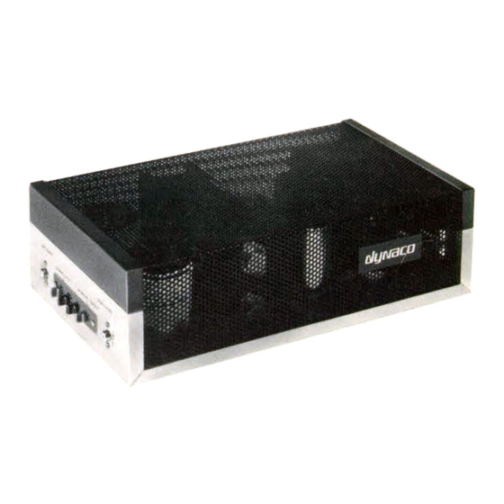
- Page 1 Stereo 80 Vacuum Tube Amplifier Owner's Manual TRIODE POWER ON OUTPUT TUBE BIAS ADJUSTMENT STEREO 80 Vacuum Tube Power Amplifier LEFT CHANNEL RIGHT CHANNEL BIAS DISPLAY POWER OFF ULTRALINEAR Stereo 80 Vacuum Tube Power Amplifier...
-
Page 2: Table Of Contents
Alternate Tube Types ............13 Minimizing Noise in the System ........14 Warranty ................15 Stereo 80 Specifications ............. 16 Schematics ................17 Stereo 80 PC Board Parts List ..........20 Please read this manual thoroughly before operating your new Stereo 80. -
Page 3: Introduction
We have included a separate buffer circuit for each of the input and driver tubes in the Stereo 80, allowing each amplification stage to function more independently, (as if each one had its own separate power supply). -
Page 4: Vacuum Tube Warm Up
We recommend that you wait at least 3 minutes after switching the amplifier on before using it. On the Stereo 80, waiting about one minute after the four bias lamps turn from “green” to “off” is a proper (minimum) warm-up period. (See section entitled Bias Adjustments - general) -
Page 5: Input Sensitivity Setting
You can set it so that the preamplifier volume control can be turned all the way up before clipping occurs in the Stereo 80. This also allows you to connect audio components, such as CD players, directly to the Stereo 80 without using a preamplifier, if desired. -
Page 6: Power On/Off Indicators And Fuses
During the first minute or so after the Stereo 80 is first switched on, all four output tube bias indicator lamps glow green. As the unit warms up, these lamps should go off, indicating the unit is ready for use. -
Page 7: Triode/Ultralinear Modes
Triode/Ultralinear Modes The Ultralinear mode is usually considered to be the “normal” mode of operation. The overall power rating of the amplifier is specified for Ultralinear mode. In Ultralinear mode, the screen grid of each output tube is connected to a tap on its associated output transformer. -
Page 8: Bias Adjustments - General
74 to 87 millivolts, (measured across each 2 ohm output tube current sensing resistor - R20, 21, 120, or 121). The correct bias current setting for the EL34 output tubes used with the Stereo 80 is: 40ma +/- 5ma Before bias adjustments are made, the amplifier must be fully warmed up. -
Page 9: Output Tube Bias Adjustment Procedure
Output Tube Bias Adjustment Procedure 1) Warm up amplifier for 15 minutes (or more). 2) Turn off any equipment connected to the amplifier inputs and ensure that the Bias Display On/Off switch is ON. 3) Using the adjustment tool provided with the amplifier, adjust each 25-turn trimmer potentiometer to a point where its lamp does not glow. -
Page 10: Burn-In Procedure For New Output Tubes
Note: This procedure applies only when you have installed new output tubes which have not yet been burned-in. (The tubes installed on your new Stereo 80 have already been burned-in at the factory.) Also see section entitled: Tube Replacement. 1) Turn off any equipment connected to the amplifier inputs. -
Page 11: Tube Replacement
The characteristics of this noise can vary a great deal, such as: “excessive hiss,” “sputtering,” “rustling noises,” etc. If a noise problem occurs with your Stereo 80, 99% of the time it will be due to a faulty tube. Vacuum tube equipment owners become familiar with tube noises and usually become less alarmed by them as time goes on. - Page 12 1/2 years when the amplifier is used 4 hours per day (or 5 years when used 2 hours per day). The most likely source of tube noise in the Stereo 80 is the 12AT7 input tube - V1 (left channel) or V5 (right channel).
-
Page 13: Alternate Tube Types
Some audiophiles feel strongly about which manufacturer and/or particular version of vacuum tube to use for specific applications. The tubes installed on your new Stereo 80 have been selected to provide the best sound and long life. -
Page 14: Minimizing Noise In The System
Minimizing Noise in the System Hum is caused by amplification of the 50 or 60 Hz AC power line signal that is transmitted via the magnetic fields around power transformers and power cables. RF interference usually comes from inadequate shielding of cables or components. If any of these types of noises are encountered, one or more of the following pointers concerning proper component positioning and grounding may be of use: Ensure that each system component, especially the preamplifier, is located far enough away from the other components so that they will not pick up hum from them, and that the AC power cables are not... -
Page 15: Warranty
Warranty For three years from the date of purchase (one year for tubes) Dynaco will repair, for the original owner, any defect in materials or workmanship that occurs in normal use, without charge for parts or labor. It is the owner's responsibility to provide transportation to the authorized Dynaco service representative who will perform warranty service, and to present proof of purchase in the form of a dated sales slip when requesting service. -
Page 16: Stereo 80 Specifications
Stereo 80 Specifications POWER OUTPUT 40W per channel into 2, 4, or 8 ohms POWER BANDWIDTH: 40W from 17Hz to 75kHz (-3dB points) < 1% @ full power @ 1kHz<.05% @ 1W @ 1kHz, matched output tubes FREQUENCY RESPONSE 2Hz to 60kHz (-3dB points) INPUT SENSITIVITY .3V for full power output (Input Sensitivity Control set to maximum) -
Page 20: Stereo 80 Pc Board Parts List
Stereo 80 PC Board Parts List Resistors 39 ohm, 1/2W, metal film R220 49 ohm, 1/2W, metal film R4, 104 100 ohm, 1/2W, metal film R201A, 201B 127 ohm, 1/2W, metal film R64, 66 301 ohm, 1/2W, metal film R2, 3, 5, 10, 11, 102, 103, 105, 110, 111... - Page 21 Stereo 80 PC Board Parts List (cont.) Semiconductors 2.5A, 1KV D1 through D11 1N5242B (12V, 1/2W Zener) ZD1, 4, 7, 10 1N 5388 (200V, 5W Zener) ZD2, 3, 5, 6, 8, 9, 11, 12 3506 (35A, 600V Bridge Rectifier) FWB1...
Need help?
Do you have a question about the Stereo 80 and is the answer not in the manual?
Questions and answers