Table of Contents
Advertisement
Quick Links
Advertisement
Table of Contents

Subscribe to Our Youtube Channel
Related Manuals for multicomp pro MP700499


Summary of Contents for multicomp pro MP700499
- Page 1 PORTABLE BATTERY TESTER MP700499 - MP700502...
-
Page 2: Table Of Contents
Contents Introduction ................4 Checking Package Contents ............4 Safety Notes ................6 Usage Notes ................8 Chapter 1 Overview ..............10 1.1 Overview ........................10 1.2 Features ........................10 1.3 Names and Functions of Parts ................... 11 1.4 Measurement steps ....................13 1.5 Dimensions ......................... - Page 3 5.3 Canceling the Memory Function ................37 5.4 Reading Out Stored Data ................... 37 5.5 Clearing Stored Data ....................38 5.6 Download stored data ....................41 Chapter 6 Other Function ............43 6.1.Averaging Function ....................43 6.2 Auto-hold Function ....................44 6.3 Auto-memory Function ....................
-
Page 4: Introduction
Introduction Thank you for purchasing Multicomp-Pro MP700499 Battery Tester. To obtain maximum performance from the product, please read this manual first, and keep it handy for future reference. Registered trademarks Windows and Excel are registered trademarks of Microsoft Corporation in the United States or other countries. - Page 5 Carrying Bag 9803 USB Cable zero adjustment block 9363-B Pin Type test lead Lithium battery Battery Charger (Chinese standard) Option 9363-A Test Clip (British standard) (European standard) Battery Charger...
-
Page 6: Safety Notes
Safety Notes The instrument is designed to conform to IEC 61010 Safety Standards, and has been thoroughly tested for safety prior to shipment. However, using the instrument in a way not described in this manual may negate the provided safety features. Before using the instrument, be certain to carefully read the following safety notes. - Page 7 Accuracy We define measurement tolerances in terms of f.s. (full scale), rdg. (reading) and dgt. (digit) values, with the following meanings: f.s. (Maximum display value) This is usually the maximum display value. In the instrument, this indicates the currently used range. rdg.
-
Page 8: Usage Notes
Usage Notes Installation environment Operating temperature and humidity ranges 0°C to 40°C 80%RH or less (no condensation) Storage temperature and humidity ranges 23 ±5°C 80%RH or less (no condensation) Installing the instrument in inappropriate locations may cause a malfunction of instrument or may give rise to an accident. - Page 9 Do not test the terminal-to-ground voltage over 70 VDC. Do not test AC voltage. Be sure to connect the test lead correctly. Wear gloves of rubber or similar materials during measurement. Ensure sufficient ventilation when testing batteries in the measurement room to prevent explosions.
-
Page 10: Chapter 1 Overview
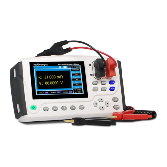
Chapter 1 Overview 1.1 Overview The MP700499 measures internal resistance, voltage, and terminal temperature of lead-acid, nickel-cadmium, nickel-hydrogen, and other types of batteries, enabling you to determine if the battery is worn out. The measurement data can be copied to a computer by connecting the instrument to a computer after measurement with the USB cable provided. -
Page 11: Names And Functions Of Parts
Small size The instrument has a similar size with A5 paper,easy to carry. Users will be not tired after long time operation since the instrument gross weight is only 800g. Model 9363B Pin Type Lead Using the model 9363B Pin Type Lead with a pin tip designed to fit in holes of φ5 mm enables measurement without removing terminal covers. - Page 12 loop. Set up automatic range test Invokes the stored test value Execute zero ajustment function Holds or cancels the measurement values Switch system setup interface Deletes the settings Stores display value to memory Selects a configuration setting or changes the value. Exit the Settings Confirms the settings.
-
Page 13: Measurement Steps
Rear view 1.4 Measurement steps The measurement process is shown as below: Measurement 1. Install the neck strap preparation 2.Check the remaining batteries of the instrument 3. Connect the test lead 4. Turning the Power ON/OFF 5. Set the clock Setting the 1. -
Page 14: Dimensions
1.5 Dimensions... -
Page 15: Chapter 2 Preparing For Measurement
Chapter 2 Preparing for Measurement 2.1 Attaching the Strap Attaching the strap to the instrument allows you to use it with the strap around your neck. Follow the procedure below to attach the strap. 1. Switch off the instrument and remove the test leads. 2. -
Page 16: Installing/Replacing Alkaline Batteries
2.2 Installing/Replacing Alkaline Batteries Before using the instrument for the first time, load the eight alkaline batteries (LR6) or the lithium rechargeable battery. Before measurement, check that the instrument has sufficient remaining battery power. If the remaining battery level is low, replace the batteries. See the battery indicator to check the remaining battery level. - Page 17 LR6 battery replacement Lithium battery replacement...
-
Page 18: Connecting The Test Leads
2.3 Connecting the Test Leads To avoid electric shock accident, connect the test leads correctly. To be safe, do not use any test lead other than the ones specified by our company. The ends of leads are sharp. Be careful to avoid injury. ... -
Page 19: Clock Function
2.5 Clock Function Date and time can be set in the system setup interface. Check the clock Settings the first time you use this device. 2.5.1 Set the date 1. Press the [SET] key on the test page twice to switch to the system setting interface. 2. - Page 20 2.5.2 Set the clock 1. Press the [SET] key on the test page twice to switch to the system Settings interface. 2 Select the relevant options. Press the direction key to move the cursor position, press the [ENTER] key to select the time, and then press the direction key to adjust the value at the corresponding position.
-
Page 21: Chapter 3 Basic Measurement
Chapter 3 Basic Measurement Before measurement, be sure to read this chapter. To avoid electric shock accident and short circuit, please operate the instrument as following: Do not test the voltage over 70 VDC Do not test the terminal-to-ground voltage over 70 VDC. ... -
Page 22: Setting The Measurement Range
Inspection item Action Touch the test lead to the zero adjustment board. If Is he fuse burned out? the resistance display still shows [−−−−], the fuse Is the test lead might be burned out or the test lead may be disconnected? disconnected. - Page 23 The zero adjustment function displays subsequent measurement results using the measured value (correction value) obtained when it was performed as zero. The function is able to get a more reliable accurate measurement result. It is recommended to use zero function before measurement. ...
- Page 24 9363-B pin type test lead Be sure to connect each of the DRIVE and SENSE terminals by inserting the tip of the pin into the holes on the zero adjustment board. (See the figure above.) Do not place the zero adjustment board on top of the battery or any metal. Electromagnetic induction effect could result in unstable measurement values.
-
Page 25: Retaining The Displayed Values
3. Press the key [ENTER] to perform zero adjustment. If the test leads are not shorted while the display is blinking, it will result in an error. When the screen shows error information: The error message is displayed without the correct compensation value. -
Page 26: Determining Battery-Wear Judgment Values
When the warning display or voltage is displayed as [−−−−], the values cannot be retained. Changing any of the settings cancels retaining. Turning off the power cancels retaining. 3.5 Determining Battery-wear Judgment Values 1. Please refer to "pre-operation inspection of section 3.1" to set the range and zero operation. 2. - Page 27 Select relevant options [ENTER] Press the direction key to move the cursor position, press to select the temperature measurement, and then press the left and right keys to turn on and off the temperature measurement function. 3. Press [ENTER] to store the setting of temperature measurement function, and press [ESC] return to the measurement interface.
-
Page 28: Chapter 4 Comparator Function
Chapter 4 Comparator Function 4.1 Overview The battery measurement values can be compared with the present threshold values using the comparator function to determine the ranges in which the values fall within: PASS, or FAIL. Up to 200 comparator conditions can be set. A buzzer sounds when the test result is not qualified in the range. -
Page 29: Set The Comparator Group Number
Press the direction key to move the cursor to the mode position, press the [ENTER] key to select the comparison mode, and then press the left and right keys to set the comparison mode R, V or RV. Press [ENTER] to store the comparison mode. - Page 30 Press the direction key to move the cursor, press [ENTER] to select the comparator switch, and then press the left and right keys to turn the comparator on or off. 2. Press the direction key to move the cursor to the resistance range position. Press [ENTER] to select the resistance range to be set, and then press left and right to set the...
- Page 31 2. Press the direction key to move the cursor to the voltage range position. Press [ENTER] to select the voltage range to be set, and then press the left and right keys to set the voltage range. Press [ENTER] again to complete. Press [ESC] to return to the measurement interface.
- Page 32 Press [ENTER] to select the upper limit of resistance to be set, press left and right keys to move the cursor, and press up and down keys to set the upper limit of resistance. Press [ENTER] again to complete. 3. Press the direction key to move the cursor to the lower resistance position. Press [ENTER] to select the lower limit of resistance to be set, press left and right keys to move the...
-
Page 33: Setting The Comparator Buzzer
Press [ENTER] to select the voltage upper limit to be set, press left and right to move the cursor, [ENTER] and press up and down to set the voltage upper limit. Press again to complete. 3. Press the direction key to move the cursor to the lower voltage position. Press [ENTER] to select the voltage lower limit to be set, press left and right to move the cursor,... - Page 34 [SET] 1. Press on the test page. Switch to the comparator interface. 2. Press the direction key to move the cursor to the signal. Press [ENTER] to select the mode of message ringing that needs to be set, and press the left and right keys to switch between qualified ringing and unqualified ringing.
- Page 35 • The range keys cannot be used while the comparator function is turned on. • If there are no measurement values, [−−−−] is displayed and a comparator judgment cannot be performed. • Even when the power is turned off, the comparator settings are saved and the comparator will be restored to on when the power is again turned on.
-
Page 36: Chapter 5 Storage Function
Chapter 5 Storage function 5.1 Overview This instrument can store up to 2400 sets of data combining presently measured values*( Date and time, resistance, voltage, temperature, comparator threshold values, and results of judgment). After measurement, saved data can be displayed or transferred to a computer. The structure of the internal memory is as follows: Memory Structure Unit name... -
Page 37: Canceling The Memory Function
1. If the data is stored at a different address than the memory address shown, use the key to change the address cell number. This can be done at any time as long as storage is enabled. 2. Retain the measurement values by pressing the [HOLD] key. -
Page 38: Clearing Stored Data
2. Use the key to select the memory number to be read out. Use the key locate the memory number The measurement values for the selected memory number are displayed. Press the DATE key to check the date and time when the data was stored. ... - Page 39 2. Press to select the memory address unit. Press to select a place. 3. Press [CLEAR] to delete the current group of data. 4. Press [ENTER] again to confirm that the data stored in the selected memory address is deleted. 5.5.2 Clearing a cell (200 groups) of data 1.
- Page 40 4. Press [ENTER] again to confirm that the data stored in the selected cell is deleted. 5.5.3 Clearing All Data [FILE] 1. Press on the test page. Switch to the file reading interface. 2. Press to select the memory address unit. Press to select a place.
-
Page 41: Download Stored Data
1.Connect one end of the 9803 USB communication cable to the personal computer and the other end to the PC interface above the MP700499. 2. When the cable is connected, USB small icon appears in the status bar above the tester, and the... - Page 42 3.Open the 3554DISK, the data is stored in the FILE_A、FILE_B and other files inside, which can be downloaded according to the need. Open as follows: Battery Test Serial Number HP3554 Test Start Date&Time 00-268470120 05:00:15469 Memory Location Battery Location Battery Type Battery No.
-
Page 43: Chapter 6 Other Function
Chapter 6 Other Function 6.1.Averaging Function This function averages the measurement values in order to display a single value. It helps to stabilize fluctuations in the measured values. When the test value is not stable, the average function can be used. The average number can be selected as 2, 3, or 4. -
Page 44: Auto-Hold Function
The average function can be used when measure resistance values. The average function is used to change the display update rate of the test value. When the average function is not used, select "OFF". 6.2 Auto-hold Function This function automatically recognizes the stability of measurement values and retains them. -
Page 45: Auto Power Save Function
2. Press the direction key to move the cursor to the automatic storage function. [ENTER] Press the key to turn ON or OFF the automatic storage function, and press the left and right keys to switch OFF, ON. Press [ENTER] again to complete. -
Page 46: Battery Level Warning
1. Press [SET] on the test page. Switch to the system Settings interface. 2. Press the direction key to move the cursor to automatic shutdown. Press [ENTER] to select the automatic shutdown function, and press the left and right keys [ENTER] [ESC] to switch OFF, ON. -
Page 47: Chapter 7 Specifications
Chapter 7 Specifications 7.1 General Specifications Model MP700499 MP700500 MP700501 MP700502 Display 4.3” VFD display 4.3”TFT LCD Display Measurements ESR, DCV Resistan Accura ±1% ±0.5% Range 0.001mΩ~3.100Ω 0.001mΩ ~ 30.100Ω Voltage Accura ±0.02% ±0.02% Range 0.0001V~60.000V 0.00001V~100.0 0.00001V~300.0 0.00001V~1000.0 Signal Source AC 1kHz test AC 1kHz open circuit voltage: <5VTest current <150mA... - Page 48 Timer Feature 24-hour clock; leap years are adjusted automatically Accuracy About ±4 min per month. Built-in backup lithium battery Other Battery life: about 2 years Operation keys Plastic keys Display LCD screen Accuracy guarantee 1 year 0°C to 40°C Operating temperature and humidity 80%RH (no condensation) -10°C to 60°C Storage temperature and humidity...
-
Page 49: Chapter 8 Maintenance And Service
Chapter 8 Maintenance and Service 8.1 Repair, Inspection, Cleaning Customers are not allowed to modify, disassemble, or repair the instrument. Doing so may cause fire, electric shock, or injury. When the instrument is being repaired, batteries and parts should be removed to prevent damage during transportation. -
Page 50: Chapter 9 Appendix
Chapter 9 Appendix 9.1 Effect of extended test line and induced voltage Test lines can usually be extended by customization. If you want to extend the test line, please contact the dealer or Multicomp-Pro. The user can not extend the test line privately. Reduce induction voltage Because the instrument under AC power to test resistance with very small resistance, the inductive voltage will affect the test. -
Page 51: Ac 4-Terminal Measurement Method
9.3 AC 4-terminal Measurement Method The instrument uses AC four-terminal measurement method, so when measuring resistance, it is not necessary to consider the internal resistance of the test line and the contact resistance between the test line and the object under test. The AC current (Is) flowing from the SOURCE port of the instrument flows through the tested battery.
Need help?
Do you have a question about the MP700499 and is the answer not in the manual?
Questions and answers