
Related Manuals for eddyfi R-Scan Array

Summary of Contents for eddyfi R-Scan Array
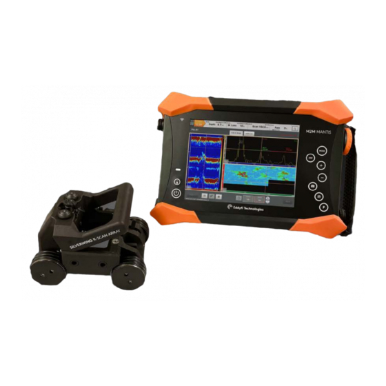
- Page 1 User’s Manual R-SCAN ARRAY Semi-automated phased-array corrosion mapping solution.
- Page 2 The following documentation is protected by copyright. All rights reserved. Eddyfi reserves the right to continue developing the system and software without documenting each individual case. Eddyfi holds no responsibility for any damage or destruction caused when following instructions within this manual.
-
Page 3: Table Of Contents
System Storage ........................18 System Encoder Resolution ....................18 System Technical Specifications ................... 18 R-Scan Array Specifications ....................19 R-Scan Array Setup and Operation ..................20 Manual mode ........................20 Manual mode scanning pattern ..................21 Automatic mode ........................ 22... - Page 4 R-Scan Array Maintenance ....................23 Technical Support ........................24 Troubleshooting ........................24 Maintenance ......................... 25 Handle replacement ......................25 Probe lock cam lever and plunger replacement ..............26 Rear probe lock cam lever ....................26 Side Probe lock cam lever ....................27 Wheel Brake Shoe replacement ...................
-
Page 5: Precautions And Conventions
Precautions and Conventions... -
Page 6: General Precautions
R-Scan Array system. All magnetic products should be kept at a safe distance from individuals with such devices. -
Page 7: Conventions
Do not ignore caution indications, ensure the condition is understood before proceeding. TETHER LINE A suitable safety line must be attached to the handle of the R-Scan Array scanner during manual operation. Attach the tether line BEFORE placing the R-Scan Array scanner onto the inspection surface. - Page 8 (90) days from the completion of repair. Upon Customer’s written notice of defect within the ninety (90) day period, EDDYFI will replace the defective part(s) and/or re-perform the service. This warranty is limited to failures in areas directly related to the repair performed. EDDYFI does not warrant any non-EDDYFI products.
-
Page 9: Copyrights
Eddyfi UK Ltd. Under copyright law, copying includes translation in other languages and formats. -
Page 10: R-Scan Array
R-Scan Array... -
Page 11: Introducing R-Scan Array
Introducing R-Scan Array R-Scan Array PAUT system is the perfect solution for the inspection of complex geometry components including curved surfaces, flat plate, pipelines, and restricted access areas. The versatile, battery-operated, portable semi-automated Phased-Array (PA) corrosion mapping solution with onboard data collection capabilities delivers improved inspection dexterity and accuracy. -
Page 12: What's In The Box
What’s in the Box This depends upon which package of the R-Scan Array system has been purchased. R-Scan Array The R-Scan Array package is supplied in a rugged transport case and comes with the following standard accessories: Nanuk transport PELI-CASE •... -
Page 13: R-Scan Array Overview
R-Scan Array Overview Scanner Components Figure 2: R-Scan Array Scanner components 1. Phased-array Probe 3. Foam Seal Typically paired with a 7.5 MHz 64 Provides a watertight seal between the Element Linear Array 1mm pitch probe. water box and the inspection surface. -
Page 14: Front Isometric View
Front Isometric View Figure 3: R-Scan Array Front isometic view 5. Handle 7. Indexing button Used to carry, deploy, move, and remove Identified by an illuminated blue LED. the scanner. It is also used as a tether Button has two functions: point for the scanner. -
Page 15: Rear Isometric View
Rear Isometric View Figure 4: R-Scan Array rear isometic view 11. Probe Lock 13. Wheel brake Two probe lock levers are used to clamp Used to hold the scanner in position on the water box securely to the scanner the inspection surface. The wheel brake chassis. -
Page 16: Magnetic Wheels
Magnetic Wheels Figure 5: R-Scan Array wheel identification Figure 6: Transit case keeper plate 14. Low friction wheels 16. Keeper Plate Are identified by a smooth wheel surface. Used to safely store the low friction set Designed to be used for automated PA of wheels in the transit case and control scanning. -
Page 17: Water Box
Water box Figure 7: R-Scan Array water box 18. Water inlet 20. Water box wedge column Irrigated couplant feed that connects to An interchangeable wedge provides a the 8mm OD hose in the umbilical. column of either 15mm or 30mm. The... -
Page 18: R-Scan Array General Specifications
110mm (4.3in). • be free of excess rust, scale, ferrous debris, oil, ice, frost or any organic growth. System Storage When storage of the R-Scan Array system is required, it must be stored: • in the supplied transit cases. •... -
Page 19: R-Scan Array Specifications
R-Scan Array Specifications The table below lists specification of the R-Scan Array system. Dimensions (w × d × h) 117 × 159 × 116 mm (4.6 × 6.2 × 4.5 in) Weight without probe 1.2 Kg (2.6 lbs) Circumferential scanning... -
Page 20: R-Scan Array Setup And Operation
R-Scan Array Setup and Operation Manual mode To prepare and connect the system together for a manual inspection: Power on the PA UT instrument 2. Connect the probe cable and encoder cable to the instrument. 3. For a manual mode inspection ensure the high friction wheels are in place on the scanner. -
Page 21: Manual Mode Scanning Pattern
13. Connect the water hose to the pump. 14. Attach a tether to the handle of the scanner. 15. Using the Eddyfi PA UT instrument follow the onscreen setup instructions paying particular attention to the following options: a. In Specimen ensure the thickness value of the test item is entered correctly. -
Page 22: Automatic Mode
For an automatic mode inspection fit the low friction wheels to the scanner. 2. Disengage the wheel brake lever. 3. Attach R-Scan Array scanner to the RMS scanning head using the supplied quick release bracket. 4. Follow the setup instructions found in RMS-PA User guide. -
Page 23: R-Scan Array Maintenance
R-Scan Array Maintenance... -
Page 24: Technical Support
Technical Support For technical support, please contact: support@eddyfi.com Troubleshooting Problem Possible Cause Action Encoder not Instrument setup Refer to the instrument’s documentation functioning regarding encoder setup / calibration. Encoder cable Check the encoder cable plug is making full contact with the corresponding socket. -
Page 25: Maintenance
Maintenance After each inspection, it is recommended that: • the R-Scan Array scanning head is dried after every use. • any dirt or debris are removed from the wheels. • the system is packed into the transit case with the umbilical assembly. -
Page 26: Probe Lock Cam Lever And Plunger Replacement
Probe lock cam lever and plunger replacement Gaining access to the rear and side probe lock cam are different, but once accessible the replacement procedure for the probe lock cam and plunger is identical. Rear probe lock cam lever From beneath remove the two pozi screws securing the dust cover to the rear fairing. Figure 13: Rear fairing dust cover screw location 2. -
Page 27: Side Probe Lock Cam Lever
outward. Push the lever down and the plunger retracts inwards. 8. Replace the rear fairing and dust cover. Side Probe lock cam lever Remove the two countersunk bolts securing the right-side cover. Figure 18: Right-side cover front bolt location Figure 17: Right-side cover rear bolt location 2. -
Page 28: Wheel Brake Shoe Replacement
Wheel Brake Shoe replacement The wheel brake sits on top of the replaceable brake shoe. To replace: From beneath remove the two pozi screws securing the dust cover to the rear fairing. Figure 22: Rear fairing dust cover screw location 2. -
Page 29: Wheel Replacement
Wheel Replacement The wheels of the scanner can be changed between low friction and high friction wheels. To replace: Remove the two socket cap screws from the wheels Figure 26: Wheel bolt location 2. Carefully pull the magnetic wheels away from the wheel hub. WARNING Magnetic wheels, risk of figure trap. -
Page 30: O-Ring Replacement For High Friction Wheels
O-ring replacement for high friction wheels The high friction wheels have 3 O-rings that sit within groves around the wheel. To replace: Remove the two socket cap screws from the wheels that requires replacement O-rings. Figure 29: Wheel bolt location 2. - Page 31 The information in this document is accurate as of its publication. Actual products may differ from those presented herein. © 2021 Eddyfi UK Ltd. Eddyfi, Silverwing, RMS, R-Scan Array CMAP, Gekko, Mantis and their associated logos are trademarks or registered trademarks of Eddyfi in the United States and/or other countries.
Need help?
Do you have a question about the R-Scan Array and is the answer not in the manual?
Questions and answers