Table of Contents
Advertisement
Quick Links
Advertisement
Table of Contents

Related Manuals for Formax Cut-True 31H


Summary of Contents for Formax Cut-True 31H
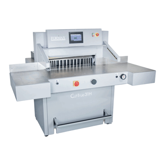
- Page 1 Cut-True 31H Hydraulic Guillotine Paper Cutter OPERATOR MANUAL Rev. 3 4/2021...
-
Page 2: Table Of Contents
CONTENTS 1. 1. G ENERAL INFORMATION ..................1 1.1 Identi cation ......................1 1.2 Purpose of use ....................... 2 1.3 Documentation ..................... 2 1.4. Organizational measures / receipt of operating instructions....2 2. SAFETY OF USE......................3 2.1 Symbols: meaning and application ............... 4 2.2 Employee quali cations .................. - Page 3 5.3 Electrical apparatus .................... 25 6. POWER SUPPLY......................26 7. USING OF THE CUTTER .................... 27 7.1 Work area for operational sta ............... 27 7.2 Danger zones in the cutter ................27 7.3 Starting up the cutter ..................27 7.3.1 Starting the cutter ..................27 7.3.2 Indications (diagnostics) of the safety curtain after switching on the power supply.
-
Page 4: General Information
1. GENERAL INFORMATION This operator manual introduces the machine for the user and shows what the machine was designed for to enable safe and comfortable work. Please take note of the special safety requirements necessary to use the cutter. The manual should be stored near the cutter and be easily accessible. -
Page 5: Purpose Of Use
1.1 Purpose of use The Cut-True 31H Guillotine Cutter is designed for cutting paper, cardboard and other materials like plastic and laminated films. It is mainly used by printing houses, print finishing specialists, copy shops and offices. In the case of some materials (like plastics) it is recommended to cut a smaller stack than maximum specified. -
Page 6: Safety Of Use
2. SAFETY OF USE The mechanical, electrical and electronic cutter assemblies were made according to state-of-the-art solutions and generally accepted technical rules that ensure safety in the event of a failure. Appropriate safeguards provide the operator with the highest level of security. The use of accessories or accessories that have not been mounted, delivered or manufactured by the cutter manufacturer requires a special permission from the manufacturer. -
Page 7: Symbols: Meaning And Application
2.1 Symbols: meaning and application Table 1. Symbols meaning Read operator manual Respect operator manual INFORMATION WARNING! Risk of machine damage Risk of deterioration of technical condition of machine CAUTION! DANGER! Danger to life Danger of body damage Dangerous electrical voltage! Children must not operate the device! Do not put hands underneath the knife! Do not leave knives unattended... -
Page 8: Employee Quali Cations
2.2 Employee qualifications The guillotine can only be operated by qualified employees who have been properly trained. Such employees must be of legal age. Every employee assigned to work during assembly, disassembly, reassembly, commissioning, servicing and maintenance (technical inspection, servicing, repairs) of the cutter must read the entire operating manual, in particular the chapter "Safety of use". -
Page 9: Expected Risks When Operating The Cutter
2.4 Expected risks when operating the cutter DANGER! The operator must operate the machine in good technical condition. At the beginning of each work shift and after each knife replacement, check the operation of the safety devices. B y n o t c h e c k i n g t h e m , there is an increased chance of bodily injury or damage to the cutter. -
Page 10: Description And Evaluation Of Residual Risk
2.5 Description and evaluation of residual risk The manufacturertakes responsibility for the construction of the cutter in order to eliminate the danger, although some risk elements during the cutting machine operation are possible. Residual risk may result from incorrect behavior of the cutter operator. -
Page 11: Safety Systems Used In The Cutter
2.6 Safety systems used in the cutter • Two-button engagement - the cutter is operated using the two-handed cut start system • LED Safety Curtain - an optoelectronic device that creates a safety curtain • Control system - position control at the upper turning point of the knife and the pressure beam. - Page 12 Figure 3. Arrangement of covers and protective elements Table 3. Safety measures used to eliminate hazards (according to Figure 3) Identification Factors and/or Security measures dangerous ares 1,3,4,10,1 The lever assembly fixed cover mechanism of the machine body pressure beam drive ...
- Page 13 4. The screw mechanism of - machine body the backgauge drive - fixed cover 6,12 1,3,4,10,1 fixed cover Motor, lever mechanism machine body of the knife drive front table mechanism emergency stop - fixed cover Approach move of the safety curtain ...
-
Page 14: Safe Working Rules
- closed housing 2,13 Direct contact of active - partially reduced voltage elements supply to the control system up to 24V AC/DC. - protection against indirect contact according to PN-EN Indirect touch 60204-1 - continuity of the protective conductor 2.8 Safe working rules 1. -
Page 15: Safety Control
2.9 Safety control Periodic security check should be carried out in accordance with the law. These provisions concern: accident prevention guarantee of efficient work and precision of operation eliminating production stoppages. INFO Following a maximum of 5 years of use, the following functions should be carried out and the results should be documented. -
Page 16: Transport
3.2 Transport The box with the machine should be transported in accordance with the markings on it (fig.4). When using a forklift (Fig. 5a), make sure that the fork length is suitable so that you can grasp the entire depth of the box. Figure.4 Cutter in transport package... - Page 17 Figure 5a. Transporting the cutter in the shipping case using a forklift. Figure 5b. Transporting the cutter outside the shipping case using a pallet truck...
-
Page 18: Delivery Status
3.3 Delivery status The cutter is shipped with the side tables unassembled. Assemble the tables according to Figure 6 below. Fig 6. Tightening of side tables 1. Left side table + screw M10x20 (4 pcs) + washer 8 (4 pcs.) 2. -
Page 19: Setting The Cutter
3.4 Setting and leveling the cutter Figure 7. Adjusting the cutter leveling foot. The cutter does not need to be attached to the ground. The correct and safe setting of the machine is achieved by turning the leveling foot (1), and locking its position with the nut (2), as shown in Figure 7. -
Page 20: Work Area
3.5 Work area In order to easily access the cutter's mechanisms during adjustment, maintenance or service activities, it is recommended to maintain a free space of about 0.5m/1.5 feet around the device. (Fig.8) Figure. 8... -
Page 21: Technical Characteristic Of The Cutter
4. TECHNICAL CHARACTERISTIC OF THE CUTTER 4.1 Purpose The cutter is intended for trimming the required size of paper, cardboard and other materials: plastics, fibers, metal foil, laminate, rubber, etc. It is mainly used in printing houses, bookbinding shops and offices. 4.2 Main parameters 4.2.1 Technical data Table... -
Page 22: Technical Data
4.2.2 Technical data- electronics scheme Table 5. Parameter Maximum power (kW) Voltage / frequency 400/50 - 60 (V/Hz) 3x20 Fuse (A) 3x30 4.2.3 Technical data- hydraulic system 4.2.3.1 Technical data- hydraulic appratus Table 6. Parameter Motor power (kW) 3x400/50 Voltage / frequency (V/Hz) 2x220/60 Control of executive elements (VDC) -
Page 23: External Dimensions
4.2.4 External dimensions The dimensions of the cutter are shown in Figure 9 and Table 6. Figure 9. Dimensions of the cutter Table 6. VALUE DIMENSION (mm) 1445 1754 1857 1105 Y program Y1 manual... -
Page 24: Operation
5. OPERATION 5.1 Operating safety 5.1.1 Safety instructions • Before each start-up or start-up on the cutter, the next change should be made to ensure that the safety components are complete and work properly. • The cutter can only be operated if all safety components and safeguards such as detachable covers, emergency stop switches are installed and fully functional. - Page 25 Figure 10. Control and signaling elements of the Cut-True 31H cutter 1. Main switch 2. Palm button, (emergency stop) 3. Locking button of the control system 4. Button that activates the control system. 5. Buttons enabling the cutting cycle (two-handed cutting start-up system) 6.
- Page 26 Figure 11. Receiver indicators The receiver is equipped with six LEDs informing about the operating status: Table 7. Position LED colour Indication Text Red/green Status OSSD OSSD Error indication Blue Quality of signal 1234 Blue LEDs informing about the quality of the settings, in conjunction with a flashing red color LED ERR, also indicate errors.
- Page 27 Table 8. Blue LEDs informing about the quality of the settings LEDs informing about quality Diode LED OSSD Meaning settings The setting is insufficient or It does not light up the protective field is interrupted at least no LED partially. The receiver can synchronize with the transmitter.
-
Page 28: Electrical Apparatus
Table 9. Position LED diode colour Indication Text Work status yellow indicator Error indication 5.3 Electrical apparatus The cutter is supplied with a five-core copper wire with 2.5 mm2 wire cross- section. The user's duty is to install the cutter to the electrical network with 20 A safeguards. -
Page 29: Power Supply
6. POWER SUPPLY Figure 14. Location of the nameplate Data on the plate: - 400V power supply - 50-60 Hz frequency - 3 kW power - 20 A protection WARNING The data on the plate must correspond to the current parameters in the mains! Parameters of frequency converters (inverters) are set by the cutter manufacturer and can not be changed! Cutter should be grounded! -
Page 30: Using Of The Cutter
7. USING THE CUTTER The cutter must be located in a place which will avoid the possibilities for operator injury. This includes slipping or falling due to poor grounding conditions, cable routing, or inconvenient access to the operating areas of the machine. 7.1 Work area for operational sta The working area is the front side of the cutter 7.2 Danger zones in the cutter... - Page 31 1. Set the main switch 1 (Fig. 15) to "ON" 1 2. Press the green 2 (Fig. 15) "I" button - LED 3 (Fig. 15) lights up green - the green OSSD 1 LED lights up (Fig.11) in the receiver 4 (Fig.15) After turning on the power supply with the main switch 1 (Fig.
-
Page 32: Indications (Diagnostics) Of The Safety Curtain After Switching On The Power
7.3.2 Indications (diagnostics) of the safety curtain after switching on the power supply. When the cutter is switched on, the transmitter 1 and receiver 2 are initialized (fig. 16). All transmitter and receiver LEDs will light for a moment. After initialization the receiver indicates the quality of the setting using four blue LEDs 3 (Fig.11). -
Page 33: Changing The Position Of The Backgauge With The Switch
The position of the backgauge is changed using the touchscreen control panel and the backgauge switch, gure 17. The method of determining the position of the backgauge and operating the touchscreen is described in the Touchscreen Operations section. 7.4.1 Changing the position of the backgauge using the backgauge switch BACK Figure 17 Switch in center "|"... -
Page 34: Clamping H T E M T A R E
BACK Switch in “FWD” position - backgauge toward the knife - in the direction of the arrow. Turning the switch for a short time causes the backgauge to move by 0.01 mm in the selected direction. Turning and holding the switch in the selected position causes the continuous movement of the backgauge. - Page 35 Figure 18. Operating elements when used during clamping.
-
Page 36: Changing The Clamping Force
7.5.2 Changing the clamping force The change of clamping force can be done by manual crank rotation (3, fig. 18) and reading the value of pressure on manometer (4, fig. 18) turning right - clamp pressure increases turning left- clamp pressure decreases Approximate values of the clamping force depending on the pressure value read on the pressure gauge (manometer) 4 25 bar ~ 300 daN... - Page 37 Fig. 19. Operating and signaling elements used during cutting. Cutting can be done if: 1. there is no object in the work area of the light barrier - the green OSSD (1) LED lights up (fig.11) on the receiver 1 (fig. 19). 2.
-
Page 38: Air Table
7.8 Air table The surface of the cutter table is equipped with air nozzles (1) (Figure 20). Figure 20. To turn on the air supply press the blower button on the touchscreen (2) (Figure 20). After switching on the air supply, moving the pile becomes easier. During the cutting, clamping or manual clamping (testing), the air supply is switched off automatically. -
Page 39: Removing The Knife
• Danger of injury to the operator and auxiliary personnel • Danger of injury to hands and hands in the knife area through cutting • The edge of the knife is sharp - do not touch • Do not handle the knife without the blade change safety tool handles •... - Page 40 Figure.22 8.1.1.4 Remove the two screws (1, fig. 22) securing the cover (2) and remove the cover. Figure.23 8.1.1.3 Unscrew and remove the first fastening screw (1) from the right side of the cutter bar (Fig. 23). 8.1.1.4 Switch on the power supply of the electrical system by turning the main switch knob (2) to the "I"...
- Page 41 Figure 24. 8.1.1.8. Unscrew and remove the mounting screws (1) and (2) (Fig. 24). 8.1.1.9. In place of the screws removed, screw in the blade change safety tool handle (1, fig. 25) so that it secures the knife to the cutter bar. 8.1.1.10 Unscrew and remove the screws (2, fig.
- Page 42 Figure 26. Figure 27.
- Page 43 Figure 28. 8.1.1.12 holding the blade change tool handles release the clamp by turning them 1/2 turn at a time to the left (fig. 27) and carefully pull the knife down (fig. 28). Place the removed knife into the special protective packaging (Fig. 29a - 29d) with the blade inwards and fasten it with two screws.
-
Page 44: Installing A Knife
Figure 29 c. Unscrewing / securing the transport handles Figure 29d. Fixing the knife in the packaging 1. Packaging 2. cover 3. screw 4. nut 5. Washer 6. Knife 7. Knife change holder 8.1.2 Installing a knife 8.1.2.1. Remove all adjusting screws (1, fig. 30) so that their faces are hidden in the knife bar body. - Page 45 Figure 30 B CORRECT POSITION - the adjustment screw does not protrude below the protrusion (2) in the cutter bar Figure 30 A - INCORRECT POTITION - the adjusting screw protrudes below the projection (2) in the cutter bar - unscrew the screw. WARNING The knife must be able to support its upper surface with the projection of the cutter bar.
- Page 46 Figure 31. Insert the knife so high that its upper surface will rest against the protrusion in the cutter bar (2, fig. 30). Figure 32. 8.1.2.4 Pre-attach the knife to the cutter bar by turning both transporting handles (1) to the right (fig. 32).
- Page 47 8.1.2.5 Install the fastening screws (2, fig. 32). 8.1.2.6 Unscrew both transport lugs (1, fig. 33) and replace them with the mounting screws (1 and 2, fig.33). Figure 33. 8.1.2.7 Slightly unscrew the first screw on the left side of the clamping screw (2, fig.32), taking care that the screw head does not protrude above the knife beam sliding plane.
- Page 48 Figure 34. 8.1.2.11. Screw in the bolt (2) lightly (Fig. 34) 8.1.2.12. Unscrew the fixing screws (4, fig.35) so that the knife falls under its own weight on the base bar with its entire length. 8.1.2.13. Tighten the adjustment screws (5, fig. 35) as far as they will go, so that the blade of the knife is cut into the slat, approx.
- Page 49 WARNING Performing cuts too deeply may result in shortened blade life! 8.1.2.14. Tighten the mounting screws (4, fig. 35) 8.1.2.15 Switch on the power supply of the electrical system by turning the main switch knob (3, fig. 35) to position "I". 8.1.2.16.
-
Page 50: Reversing Or Replacing The Cutting Sticks
8.2 Reversing or replacing the cutting sticks Danger! Risk of injury! The cutting quality of the bottom sheets in a stack and the speed of blunting of the knife depend to a large extent on cutting stick. Replacing or reversing the cutter stick (bar) is recommended after each knife change or in the event of breaking (not cutting) the lower sheets. -
Page 51: False Clamp
Figure 37. The method of removing cutting stick 1. Cutting stick (1) 2. Table (2) 3. Fixing pin 4. Screwdriver 8.2.1 Lift the stick (1) with a screwdriver (4, fig. 37) 8.2.2 Rotate or replace stick 8.2.3. Introduce the replaced stick into the channel between the tables (2) and place it on the dowel (3, Fig.37) Figure 38. - Page 52 Figure 39. False clamp (pressure bar) The False Clamp (Fig. 39) is stored under the front table in the place shown in Figure 40. Figure 40. Storage location of the False Clamp when not in use.
- Page 53 Danger! Risk of injury! In order to mount the insert in the pressure bar: 8.3.1 Put the insert (1, Fig. 41) under the clamp/pressure beam so that the insert pins are under the holes in the pressure beam. 8.3.2 Pressing pedal (2, Fig. 41), bring the clamp/pressure beam down so that the insert pins hit the holes in the beam and the insert adheres the entire surface to the bottom surface of the beam.
- Page 54 Figure 41. Operating elements used when mounting the False Clamp insert in the pressure bar.
-
Page 55: Adjusting The Parallelism Of The Backgauge Beam
8.4 Adjusting the parallelism of the backgauge beam Depending on the required inclination of the backgauge beam, it must be adjusted using drawings 42 and 43. Figure. 42 How to remove the cover To adjust with the backgauge: 8.4.1 unscrew the screws (1, fig.42) 8.4.2 remove the cover (2, fig.42) 8.4.3 loosen the screws (1, Fig. - Page 56 8.4.6 lock the adjustment screws with (3) nuts (2, fig. 43) 8.4.7 firmly tighten the screws (1, fig.43) After ttesting the cutter, repeat the adjustment until parallel cutting is achieved. Figure 43. Elements of the backgauge...
-
Page 57: Maintenance
9. MAINTENANCE Danger Maintenance and lubrication work should be carried out after turning off the machine (main switch in position "0") 9.1 Daily maintenance Every day, remove all waste from the cutter and the operator's working space. 9.2 Maintenance that should be performed periodically At regular intervals, waste and dirt should be removed from hard to reach machine and surrounding areas: •... - Page 58 in contact with the guides should be carried out in the upper (Fig. 46a) and lower position of the knife body (Fig. 46b). Lubricate recommended places on both sides of the cutter. In places requiring lubrication with a grease, apply grease with a grease gun. It is enough to press the trigger of the lubricator 2-3 times.
- Page 59 Figure 44. Cover for the backgauge (1) and lead screw (2) Figure 45. Base frame covers...
- Page 60 Figure 46a. Space for lubrication of the knife assembly in its upper position. Figure 46b. Space for lubrication of the knife assembly in its lower position.
- Page 61 Figure 47. Lubrication space of the pressure beam (3), guide shaft of the backgauge mechanism (2) Figure 48. Lubricating point of the lead screw.
- Page 62 Figure 49. Lubrication point of the knife actuator (1), pressure cylinder and shaft actuator (3) Figure 50. Lubrication point of the knife assembly lever.
-
Page 63: Hydraulic Power Supply
9.4 Hydraulic power supply The overflow valve was set to 110 bar and sealed. This setting can be checked using a manometer (included) by connecting it to the manometric connection. Unauthorized change of the pressure value is unacceptable and causes the warranty for the aggregate to be lost! 9.4.1 Working conditions of Hydraulic power supply - ambient temperature of the unit from 5C- 30C,... - Page 64 Figure 51. Oil change in the hydraulic system. Danger! Danger of burns due to hot oil! Danger of hydraulic oil splash! According to the recommendations of the hydraulic power supply manufacturer, the oil in it should be replaced after a year of intensive work. To change the oil, unscrew the drain plug (2, fig.48) located in the bottom of the tank.
-
Page 65: Service
After lubrication: Using a cloth, completely remove any excess lubricant (grease, oil), especially from surfaces which come into contact with media to be cut, this includes the work table surface, he knife body and the clamp/ pressure bar. 9.5 Service 9.5.1 General recommendations •... -
Page 66: Determination Of The Causes Of The Fault
• Each fault carries a risk of injury to the operator or his assistant. • If the cutter knife jams in the cut material during cutting, do not attempt to pull the material out from under the knife. • Defects can be eliminated only by personnel with appropriate training. •...
Need help?
Do you have a question about the Cut-True 31H and is the answer not in the manual?
Questions and answers