
Related Manuals for Formax FD 120


Summary of Contents for Formax FD 120
- Page 1 FD 120 Card Cutter MyBinding.com 5500 NE Moore Court Hillsboro, OR 97124 MAINTENANCE MANUAL Toll Free: 1-800-944-4573 5/2011 Local: 503-640-5920...
- Page 2 SAFETY PRECAUTIONS Always observe the cautions and warnings given below to prevent personal injury or property damage. The degree of danger and damage that could occur is indicated on two levels by the following marks. WARNING: Ignoring this mark could result in the possibility of serious injury or even death. Ignoring this mark could result in the possibility of injury or physical damage CAUTION : The following graphic symbols indicate the various types of action to be performed or avoided. This graphic symbol indicates a forbidden action. ...
- Page 3 Use only the power supply voltage specified on the main nameplate. Using other voltages could result in a fire or an electrical shock. Keep this unit and the power cord away from heaters and heater vents. Excessive heat could melt the cover or power cord covering, and result in a fire or an electrical shock. Do not use solvent inside or near the unit (e.g. when cleaning the unit). Such solvents may damage the rubber rollers and resin inside the unit, resulting in malfunctions. Make sure that the combined power consumption of the appliances to be connected does not exceed the capacity rating of the power outlets or plug receptacles. Exceeding the capacity rating could cause the power outlets, plug receptacles, or power extension cords to overheat and catch a fire. Remove any dust that accumulates on the power plug prongs and the surface of the plug from which the prongs extend. Accumulated dust could result in a fire. If any foreign object such as metal or liquid should enter this unit, immediately turn the unit off at the power switch and disconnect the power plug from the power outlet. Failure to do so could ...
- Page 4 Do not put fingers inside during operation. This could result in injury. Always disconnect the power plug from the power outlet when the unit is not to be used for an extended period. Failure to do so could result in a fire due to leakage current if the insulation should deteriorate. Install this unit on a level, stable stand or floor, with sufficient space around it. Failure to do so could result in the unit overturning and causing injury. Do not install this unit in a location where there is excessive humidity or where contact with water is possible. Poor choice of location could result in deterioration of the insulation, a fire or an electrical shock. Disconnect the power plug from the power outlet before attempting to move this unit. Failure to do so could result in power cord damage, a fire or an electrical shock. MyBinding.com 5500 NE Moore Court Hillsboro, OR 97124 Toll Free: 1-800-944-4573 Local: 503-640-5920...
- Page 5 Precautions in Maintenance and Handling Repairs should be performed by qualified service personnel. WARNING: 2.1 To avoid the risk of electrical shock, disconnect the machine from the A.C. power source before performing any service procedure. The hardware used is METRIC. Replace hardware only with the same size as was originally used. Observe caution when cutting cable “tie‐wraps” so as not to damage the electrical wires. Note the routing of wiring harnesses, cables and the position of parts and assemblies before disassembly. They must be reassembled in the original configuration to avoid damage from moving components during operation. When using a tool generating heat such as soldering iron, take care not to damage the harnesses and cables. MyBinding.com 5500 NE Moore Court Hillsboro, OR 97124 Toll Free: 1-800-944-4573 Local: 503-640-5920...
-
Page 6: Table Of Contents
Contents 1. Introduction .................. 6 2. Specifications .................. 6 3. Control Panel .................. 6 4. Key Components ................ 8 5. Parts on Top of the Frame .............. 1 0 6. Parts on Operating Side .............. 1 1 7. Parts on Non‐operating Side ............. 1 2 8. Parts underneath the Frame .............. 1 3 9. Electric PWB Assy. ................ 1 4 10. Electrical Wiring Diagram .............. 1 7 11. -
Page 7: Introduction
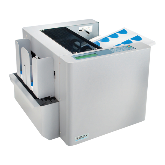
1. Introduction The FD 120 is designed to simplify business card, photo and post card cutting of paper printed by digital press, color laser printer or inkjet image printer. 2. SPECIFICATIONS Paper Size LT / Legal Size/ 9” x 14” (Max) Paper Weight 120gsm ~ 350gsm Feeder Capacity 75 sheets (200gsm) Receiving Tray 500 business cards Speed Up to 130 business cards per min Accuracy ± 0.3 mm Dimension 13.8” (W) x 15.4” (D) x 13” (H) Net Weight 60 lbs (27Kgs) Power 110/220V Selectable, 50/60Hz, 1.2A MyBinding.com 5500 NE Moore Court Hillsboro, OR 97124 Toll Free: 1-800-944-4573 Local: 503-640-5920... -
Page 8: Control Panel
3. CONTROL PANEL Note: Depending on mode, the different functions. Standard Control Panel Dealer Control Panel Keys Contro Dealer Control Panel Start and Stop the cutter Start and Stop the cutter Change job Change job Select batch count Select batch count 1. Clear paper jam in case of S3 error. Clear paper jam in case of S3 error. 2. Increment settings by 0.1 mm when pressed. Confirm job and batch count setting. 1. Confirm job and batch count setting. 2. Decrement settings by 0.1mm when pressed. Rest error and counter. Save settings N/A Enter program mode N/A Set top margin N/A Set finished length N/A Set gutter length MyBinding.com 5500 NE Moore Court Hillsboro, OR 97124 Toll Free: 1-800-944-4573 Local: 503-640-5920... -
Page 9: Key Components
4. KEY COMPONENTS Index P/N Part Name Qty Remarks 4‐1‐01 00S‐000‐6112 Switch, Power Entry 4‐1‐02 881‐102‐0002 Key Pad 4‐1‐03 881‐103‐0000 Tray, Extension 4‐1‐04 881‐104‐0000 Knob, Center Alignment 4‐1‐05 881‐105‐0000 Side Guide, L 4‐1‐06 00R‐000‐1052 Roller, Feed 4‐1‐07 881‐107‐0000 Cover, Top MyBinding.com 5500 NE Moore Court Hillsboro, OR 97124 Toll Free: 1-800-944-4573 Local: 503-640-5920... - Page 10 Index P/N Part Name Qty Remarks 4‐1‐08 881‐108‐0000 Waste Bin 4‐1‐09 881‐109‐0000 Tray, Stacking 4‐1‐10 881‐110‐0000 Cover, Safety, Rear 4‐1‐11 881‐111‐0000 Thumb Screw, Slitter Release 4‐1‐12 881‐112‐0000 Module, Slitter, 2” x 3.5” 4‐1‐13 881‐113‐0000 Roller, Ejection, Lower 4‐1‐14 881‐114‐0000 Roller, Ejection, Upper 4‐1‐15 881‐115‐0000 Belt, Slitting Transport MyBinding.com 5500 NE Moore Court Hillsboro, OR 97124 Toll Free: 1-800-944-4573 Local: 503-640-5920...
-
Page 11: Parts On Top Of The Frame
5. Parts on Top of the Frame Index P/N Part Name Qty Remarks 5‐2‐01 881‐103‐0000 Tray, Extension, Feed 5‐2‐02 881‐202‐0000 Side Guide, L, Feed 5‐2‐03 881‐104‐0000 Knob, Cutting Center Alignment 5‐2‐04 00R‐000‐1052 Roller, Feed 5‐2‐05 00S‐000‐1514 Sensor, Paper 5‐2‐06 00S‐000‐1514 Sensor, Paper 5‐2‐07 00S‐000‐1515 Sensor, Mark Reader, White 5‐2‐08 881‐102‐0001 Key Pad 5‐2‐09 00A‐000‐0207 Sensor, Paper, Black 5‐2‐10 00S‐000‐1604 Separator, Feed MyBinding.com 5500 NE Moore Court Hillsboro, OR 97124 Toll Free: 1-800-944-4573 Local: 503-640-5920... -
Page 12: Parts On Operating Side
6. Parts on Operating Side Index P/N Part Name Qty Remarks 6‐3‐01 00A‐000‐1001 Asm, PWB, Logic 6‐3‐02 00C‐000‐0083 Cable, 34 pin, 55cm, Driver Interface 6‐3‐03 00C‐000‐0071 Cable, 34 pin, 37cm, Logic Interface 6‐3‐04 00A‐000‐1121 Asm, PWB, Interface 6‐3‐05 00A‐000‐1611 Asm, PWB, LCD Interface 6‐3‐06 00C‐000‐0051 Cable, 16 pin, 47cm, LCD Interface 6‐3‐07 00C‐000‐0031 Cable, 14 pin, Panel Interface 6‐3‐08 00A‐000‐1501 Asm, PWB, Control Panel 6‐3‐09 00A‐000‐0188 Switch, Interlock 6‐3‐10 00D‐000‐0303 Display, LCD 6‐3‐11 00A‐000‐0188 Switch, Interlock 6‐3‐12 ... -
Page 13: Parts On Non-Operating Side
7. Parts on Non Operating Side Index P/N Part Name Qty Remarks 7‐4‐01 00A‐000‐1211 Asm, PWB, Power 7‐4‐02 00B‐000‐0524 Belt, 0.08P, 132MXL 7‐4‐03 881‐403‐0000 Spring, Feed Tray Tension 7‐4‐04 00M‐000‐0404 Motor, RD, 2.58V, 3A (replaced by 00M‐000‐0403) 7‐4‐05 00M‐000‐0403 Motor, SQ, 2.58v, 3A MyBinding.com 5500 NE Moore Court Hillsboro, OR 97124 Toll Free: 1-800-944-4573 Local: 503-640-5920... -
Page 14: Parts Underneath The Frame
8. Parts underneath the Frame Index P/N Part Name Remarks 8‐5‐01 00F‐000‐0003 Fan, DC, 12V 1 8‐5‐02 00A‐000‐0161 Asm, Driver Box 1 00A‐000‐1402 Asm, PWB, Driver, L298 2 8‐5‐03 00F‐000‐0401 Filter, AC Line 1 8‐5‐04 00S‐000‐6101 Switch, 115/230V Selectable 1 8‐5‐05 00T‐000‐1405 Transformer, 115/230V 1 8‐5‐06 00M‐000‐0403 Motor, SQ, 2.58V, 3A 1 8‐5‐07 ... -
Page 15: Electric Pwb Assy
9. Electric PWB Asm. Index P/N Part Name Qty Remarks 9‐6‐01 00A‐000‐1001 Asm, PWB, Logic 9‐6‐02 00A‐000‐1611 Asm, PWB, Display, LCD 9‐6‐03 00A‐000‐1121 Asm, PWB, Interface 9‐6‐04 00A‐000‐0161 Asm, Driver Box 9‐6‐05 00A‐000‐1211 Asm, PWB, Power 9‐6‐06 00A‐000‐1501 Asm, PWB, Control Panel 9.1 P/N 00A‐000‐1001 Assy, PWB, Logic 9.2 P/N 00A‐000‐1601 Asm, PWB, LCD DISPLAY MyBinding.com 5500 NE Moore Court Hillsboro, OR 97124 Toll Free: 1-800-944-4573 Local: 503-640-5920... - Page 16 9.3 P/N 00A‐000‐1121 ASM, PWB, INTERFACE 9. 4 P/N 00A‐000‐0161 ASM, DRIVER BOX MyBinding.com 5500 NE Moore Court Hillsboro, OR 97124 Toll Free: 1-800-944-4573 Local: 503-640-5920...
- Page 17 5 P/N 00A‐000‐1211 ASM, PWB, POWER 9.6. P/N 00A‐000‐1501 ASM, PWB, CONTROL PANEL MyBinding.com 5500 NE Moore Court Hillsboro, OR 97124 Toll Free: 1-800-944-4573 Local: 503-640-5920...
-
Page 18: Electrical Wiring Diagram
10. Electrical Wiring Diagram MyBinding.com 5500 NE Moore Court Hillsboro, OR 97124 Toll Free: 1-800-944-4573 Local: 503-640-5920... -
Page 19: Sensor Voltage Measurement
11. Sensor Voltage Measurement Sensors play an important role in monitoring and tracking the flow of the media inside of machine. A majority of stall conditions could be sensor related. Therefore, a digital multi‐meter (DMM) is used for measuring the voltage reading of the sensors, and assuring proper alignment. 5.1 Set DMM to 20 at the DVC section. 5.2 Using the two probes of the DMM to get voltage, one probe placed at the chassis ground of the system, while the other one probe pin 1 of the sensor connector on the interface board. 5.3 Covering the sensor, the reading of DMM should be less than 0.2V. 5.4 Uncovering the sensor, the reading of DMM should be more than 4.5V. 5.5 Mark Reading Sensors 。Seeing paper 0.2V 。Seeing mark 1.8V The range of sensor’s voltage reading is greater than 4.5V or less than 0.2V has the best state for the sensor to monitoring the media movement. The sensor connector on the sensor board has three pins. The first pin is for signal of sensor voltage reading measurement. The second pin is for VCC (5V). The third pin is for ground. Some sensors connector is 4‐pin, the 3 pin is empty; the 4 pin will be common ground. MyBinding.com 5500 NE Moore Court Hillsboro, OR 97124 Toll Free: 1-800-944-4573 Local: 503-640-5920... -
Page 20: Replace Slitter
12. Replace Slitter Open the rear cover Rotate the thumb screw loosen the Slitter Lay down the slitter and pull it out toward exit direction *Note: The slitter assembly is replaced as a whole unit. MyBinding.com 5500 NE Moore Court Hillsboro, OR 97124 Toll Free: 1-800-944-4573 Local: 503-640-5920... -
Page 21: Replace Cutting Knife
13. Replace Cutting Knife Index P/N Part Name Usage Remarks 13‐7‐04 881‐704‐0000 Knife, Upper 13‐7‐05 881‐705‐0000 Knife, Lower MyBinding.com 5500 NE Moore Court Hillsboro, OR 97124 Toll Free: 1-800-944-4573 Local: 503-640-5920... -
Page 22: Feeding Test And Permanent Count
14. Feeding Test and Permanent Count The system provides view permanent count, mark and feeding testing without cutting features Select Job #4 and set cutting mark to on by holding then tip on for 5 seconds, “test mode 23" is displayed Hold On the lower right corner of the display will show xxxx. For example, if it shows 23 means the permanent count is 23,000 Press to feed paper, the cutting knife will be off without function to make sure feeder and mark reader is OK. This will save a lot of testing time and paper as well. Press to resume. MyBinding.com 5500 NE Moore Court Hillsboro, OR 97124 Toll Free: 1-800-944-4573 Local: 503-640-5920... -
Page 23: Calibration
15. Calibrations To calibrate cutting mark, cutting length, offset and top margin: Select Job #4 Holding for 5 seconds. mark:50 length:50 offset:50 margin:50 is displayed. Tip on to select the item you are going to calibrate. Tip on to save when the calibration is done. 15.1 Length On Job #4, set it to without cutting mark mode, feed a piece of paper to cut the top margin, make sure the cut top margin is 12.7mm, if not calibrate the top margin first then do Length calibration. Select length:50. Feed a Letter Size sheet thru, the sheet will be cut into half which is 5.5”, compare the 2 X 5.5”, if the 1 half cut is shorter than the 2 half, tip on to adjust until the 1 half and 2 half are exactly the same; If the first cut is greater than the 2 half, tip on to decrease the setting until the 2 half is equal. Each press on or represents 0.1mm increment or decrement 15.1 Cutting Mark On job #4 to hold then tip on to set cutting mark, cut a printed sheet with mark, make sure the leading edge of the mark to cutting line is 3mm Select mark:50, if the cut mark leading edge to cutting line is greater or smaller than 3mm, tip on ... - Page 24 15.3 Offset This is allowing calibrate the 5 business card in a sheet which is possibly longer than the spec. Assume the 5 card length is longer than the specification by 0.1mm. Under calibration mode select offset:50 to reduce the figure 50 to 49. 15.4 Top Margin On job #4 without mark to cut the top margin, it should be 12.7mm. If the cut top margin sample is greater or smaller than 12.7mm, select margin:50, tip on and to adjust until the top margin is within the spec. Each press represents 0.1mm increment or decrement. MyBinding.com 5500 NE Moore Court Hillsboro, OR 97124 Toll Free: 1-800-944-4573 Local: 503-640-5920...
-
Page 25: Feed Tray Tension Adjustment
16. Feed Tray Tension Adjustment 16. 1 Factory setting the spring position as shown below: 16.2 If feed hopper tension set to scale 4/Thin Paper, is still causing the paper to buckle, and not get into the 1 set of transport roller, relocate the spring mounting hole to the right to reduce the tension. 16.3 If feed hopper tension set to scale 1/Thick Paper, still cannot feed the paper well and keep occurring misfeed, relocate the spring to the left to get more tension. 16.4 If the tension set tight still cannot feed well, replace the feed roller. MyBinding.com 5500 NE Moore Court Hillsboro, OR 97124 Toll Free: 1-800-944-4573 Local: 503-640-5920... -
Page 26: Feed Gap Adjustment
17. Feed Gap Adjustment 17.1 Loosen the Feed Ramp Mounting Screw on Both Sides Ramp Adjustment Screw Ramp Adjustment Screw 17.2 Press the feed ramp down to increase the gap, tilt it up to reduce the gap. MyBinding.com 5500 NE Moore Court Hillsboro, OR 97124 Toll Free: 1-800-944-4573 Local: 503-640-5920... -
Page 27: Top Margin Parallel Adjustment
17.3 Place a 600gsm (2 x 300gsm) paper underneath the 2 side roller as shown below. Press the feed tray down and pull the paper to make sure the gap is right. It should not have too much drag. 17.4 Fasten the ramp mounting screw 18. Top Margin Parallel Adjustment 18.1 Power off 18.2 Remove the rear cover 18.3 Use a 300gsm or 14 pt. sheet as a gauge, hand feed it into and against registration roller firmed. 18.4 Underneath the feed tray has 5.5mm nut to hold the side guide, loosen the nut and align it against the paper to make it straight. Fasten the nut. 18.5 Feed a sheet to cut, measure the left and right of the top margin cut is 12.7mm +/‐ 0.1mm, if not re adjust the side guide. MyBinding.com 5500 NE Moore Court Hillsboro, OR 97124 Toll Free: 1-800-944-4573 Local: 503-640-5920... -
Page 28: Self-Diagnose For Malfunction
19. Self‐diagnose for Malfunction The system provides a unique feature to help service people pin point the sensor malfunction, detailed below: Firmware Version: 01 Sensor Scan: OK 19.1 Hold then turn the power to on, is displayed 19.2 using a piece of paper to trigger the sensor, the sensor on the interface board connection are showing as below. Remove the trigger, the display will change to Firmware Version: 01 Firmware Version: 01 Sensor Scan: OK Sensor Scan: I‐20 , If the display remains, it means that sensor is bad. Sensor Connector # Function Board Connection S1 Feed Tray Sensor Interface Board I – 20 S2 Input Sensor Interface Board I – 21 S3 Paper Monitoring Sensor Interface Board I – 23 S4 Mark Reading Sensor Interface Board I – 22 ... -
Page 29: Error Message And Trouble Shouting
20. Error Message and Trouble Shooting Error Message Trouble Shooting Misfeed 1.Check S1 voltage 2.Check feed motor belt 3.Check pulley screw 4.Check motor detain torque, if no torque 5. Replace driver board Jam in Sensor 2 1.Check S2 2.Adjust the feed tray tension 3.Adjust the ramp Jam in Sensor 3 1. Check S3 2. check detain torque of transport motor, if no torque 3. Replace driver board Mark error 1. Check mark sensor voltage; see paper 0.2V 2. Seeing mark has to be greater than 1.8V 3. Change mark sensor and do mark, top margin calibration Check Top Cover Check top cover interlock switch Check Rear Cover Check rear cover interlock switch Check Waste Bin Check waste bin interlock switch Finish card not clean and neat 1. Adjust the cutting knife guiding plate, if problem still 2. - Page 30 21. Recommended Spare Parts List Index P/N Part Name 4‐1‐01 00S‐000‐6112 Switch, Power Entry 00F‐000‐3006 Fuse, Time Delay, 3.15 A, 250V 4‐1‐02 881‐102‐0001 Key Pad 4‐1‐12 881‐112‐0000 Module, Slitter, 2 x 3.5” 881‐112‐0051 Module, Perforator 881‐112‐0052 Module, Scoring 4‐1‐13 881‐113‐0000 Roller, Ejection, Lower 4‐1‐14 881‐114‐0000 Roller, Ejection, Upper 4‐1‐15 881‐115‐0000 Belt, Slitting Transport 5‐2‐04 00R‐000‐1052 Roller, Feed 5‐2‐05 00S‐000‐1514 Sensor, Paper 5‐2‐07 00S‐000‐1515 Sensor, Mark Reader, White 5‐2‐09 00A‐000‐0207 Sensor, Paper, Black ...
Need help?
Do you have a question about the FD 120 and is the answer not in the manual?
Questions and answers