Table of Contents
Advertisement
Quick Links
Advertisement
Table of Contents

Related Manuals for Formax FD 125


Summary of Contents for Formax FD 125
- Page 1 FD 125 Large Format Card Cutter OPERATOR MANUAL Rev. 2 8/2021...
-
Page 2: Table Of Contents
Table of Contents SAFETY PRECAUTIONS ................................ 3 Introduction ..................................4 Specifications ..................................4 Accessories ..................................4 Major Components and Assemblies ...........................5 Control Panel ..................................5 Setting Up Procedure ................................. 8 The Job selection ................................10 Optional Slitter……………………………………………………………………………………………………………………………………………11 Job Layout…………………………………………………………………………………………………………………………………………………..12 Registration Mark Position ............................... 15 Selecting a job ................................... -
Page 3: Safety Precautions
SAFETY PRECAUTIONS Always obs erve t he c autions a nd w arnings g iven bel ow t o pr event personal i njury or pr operty damage. Always pull the power supply plug out of its outlet before removing jammed paper. -
Page 4: Introduction
INTRODUCTION The FD 125 is designed to simplify business card, photo and post card cutting in a single pass. SPECIFICATIONS Paper Size LT, LG, LD, 12 x 18 and 13 x 19 Paper Weight 120 ~ 300gsm and Maximum<0.4mm Feeder Capacity... -
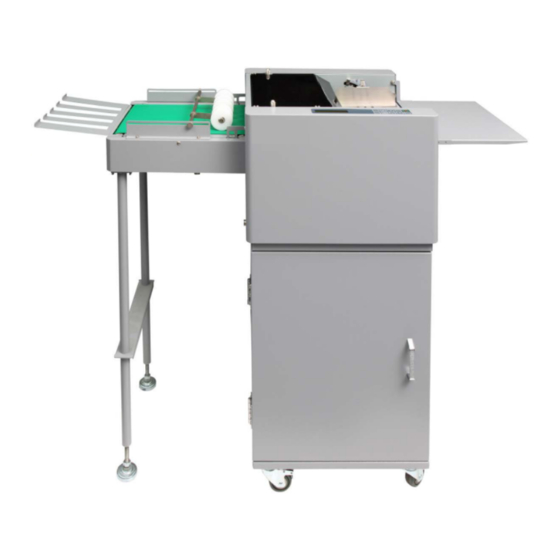
Page 5: Major Components And Assemblies
KEY COMPONENTS Cutter Stand Conveyor Optional Page 5... - Page 6 Feed Roller Cutter Asm Slitter Cassette Feed Tray Tension Scale Slitting Center Adjustment Stacking Divider 10 Stacking Tray Page 6...
-
Page 7: Control Panel
CONTROL PANEL Keys Function • Start and Stop the cutter • Change job • Toggle between “Normal Mode” and “Turbo Mode” (Paper Weight Setting Mode) • Select batch count • Pre-feed (Mark Reader Calibration Mode) • Jog forward • Increment settings by 0.1 mm when pressed. •... -
Page 8: Setting Up Procedure
SETTING UP PROCEDURE 1. CUTTER INSTALLATION Note: No tool is required for installation. Stack Tray Place the stacking divider and the stacking tray indicator shown. Power Cord caution when plugging in power cord. Plug power cord to the machine and plug the other end into the wall outlet. - Page 9 Push the feed tray down and load the paper. Readjust paper guide if needed. Adjust tray pressure. For thinner paper, the number should be higher. For heavier paper the number should be lower. Use slitter registration adjustment knob to compensate for printing registration.
-
Page 10: The Job Selection
The Job selection FD125 offers 7 different types predefined jobs from #01 to # 07 and 6 programmable job #08 to #13. The standard cassette has a slit size of 3.5” x 3 rows for business card. Optional cassettes are available. See below to select the proper slitter and program for your application. -
Page 11: Optional Slitter
Optional Slitters Slitters Finished Size Slitting Remarks Width Length Gutter Standard 882-112-010B - 3.5” 2” 1/4” 24 Up Option: 882-112-010E - 2” 3.5” 1/4” 25 Up 882-112-020A - 8.5~11” 8.5”~11” 1/4” 2 Up 882-112-030A - 5~6” 5”~6” 1/4” 4~8 Up 882-112-040A - Scoring 882-112-050A -... -
Page 12: Job Layout
Job Layout Page 12... - Page 13 Page 13...
- Page 14 Page 14...
-
Page 15: Registration Mark Position
REGISTRATION MARK POSITION Registration mark will compensate for print shifting. See below for registration mark position. Margin Feed Center SELECTING A JOB Actions Display Example #01BUSINESS CARD Turn on the power. Previous job will appear. NM 2”x3.5” W/G 23 Press until the desired job is displayed. -
Page 16: Batch Count Function
BATCH COUNT FUNCTION Batch count function is used to automatically stop the machine after a set # of sheets has been fed. Actions Display Example Press until the desired batch count number appears. The batch count will increment by 10 #04 PHOTO every time the button is pressed. -
Page 17: Turbo And Normal Mode
#10L000.0M00.0G00.0 Hold for 4 seconds. “Edit” will appear indicating machine is in “Program Mode”. #10L127.0M00.0G00.0 Hold and press to increase or to decrease change finished length in #10L127.0M12.7G00.0 Hold and press to increase or to decrease top margin in mm #10L127.0M12.7G06.0 Hold and press... -
Page 18: Reset Counter
PAPER WEIGHT Adjust paper weight settings if paper is skewing or misfeed.Set 1 or 2 for lighter paper and 4 or 5 for heavier paper. 1. Hold for 4 seconds. 2. Press to select settings 1-5. Use table below for references. 3. - Page 19 The calibration allows calibrate procedure as below: On job #4 to hold then press to set cutting mark, Cut a printed sheet with mark. Make sure the leading edge of the mark to cutting line is 3mm Select mark:50, if the cut mark leading edge to cutting line is greater or smaller than 3mm, press to adjust.
-
Page 20: Tip For Paper Weight Greater Than 300Gsm
. Paper Weight Greater than 300gsm 1. Set the feed tray tension index smaller than 3 2. Set paper weight to 5 Refer to page 18, paper weight setting 3. Squeeze down the compression spring on first set of transport roller preventing slippage. 1st set of transport roller spring... - Page 21 TROUBLESHOOTING Error Troubleshooting Out of paper Feed tray empty misfeed 1. Adjust the feed tray tension 2. Side guide too tight. Adjust side guide. 3. Fan the paper and reload into hopper jam sensor 2 1. Remove the paper jam by pulling toward stacking tray. 2.
-
Page 22: Installation Of Optional Slitter
INSTALLATION OF OPTIONAL SLITTER Optional slitters enable the FD125 to have more range of applications. Follow the steps below to the replace optional slitter cassette. 1. Lift Top Cover 2. Remove thumbscrew by turning Thumbscrews counter-clockwise on both side of the slitter cassette. -
Page 23: Optional Conveyor Item List
OPTIONAL CONVEYOR Items List 1 x Conveyor 1 x Ramp 1 x Pick-Up Rollers Assembly 1 x Interface Cable 1 x Stand Support 4 x Studs 4 x Socket Cap Screws 4 X Shoulder Washers 2 x Spacer (M6x12) 4 x Machine Screws (M4 x 12) 2 x Machine Screws (M5 x 35) 2 Thumbscrews (M4 x 12) 5 X Machine Screw (M5 x 10) 5 x Washers (M5) -
Page 24: Optional Conveyor Installation
Installation Procedure 1. Remove the side covers. 2. Remove the safety guard Safety Cover Side Cover 3. Install the 4 studs as shown using Socket 4 Cap Screws (M6x12) and 4 Lock Washers (M6). 4. Hook the conveyor onto the studs. - Page 25 8. Install Pick-Up Roller assembly using 2 thumbscrews as shown onto conveyor rails. Adjust roller distance depending on paper finish size for better stacking. 9. Install stand support using 5 x (M5 x 10) screw and washer to secure stand support to the conveyor Page 25...
Need help?
Do you have a question about the FD 125 and is the answer not in the manual?
Questions and answers