
Related Manuals for Life Fitness Run CX


Summary of Contents for Life Fitness Run CX
- Page 1 Life Fitness Run CX Treadmill (RRR-TR-0000-01) Owner's Manual/Assembly Instructions 1017719-0001 REV AA...
- Page 3 Latin America and Caribbean* Spain Hong Kong Life Fitness, LLC Life Fitness IBERIA Life Fitness Asia Pacific LTD Columbia Centre III C/Frederic Mompou 5,1º1ª 32/F, Global Trade Square 9525 Bryn Mawr Avenue 08960 Sant Just Desvern Barcelona 21 Wong Chuk Hang Road Rosemont, IL 60018 U.S.A.
- Page 4 User and Service Documents Link https://lifefitness9512.zendesk.com/hc/en-us https://www.lftechsupport.com/web/document-library/documents Additional information is available online using the links above. أ علاه إل ر إبط باستخدإم إ لإ ن تر نت على إضافية معلومات تتوفر 点击上面的链接可在线获取更多信息。 Flere oplysninger er tilgængelige online gennem linket ovenfor. Bijkomende informatie is online beschikbaar via bovenstaande link.
-
Page 5: Table Of Contents
2XL Corporation. PureGreen 24 is a trademark of Pure Green. © Copyright 2021, Life Fitness, LLC. All Rights Reserved. Life Fitness, Hammer Strength, Cybex, ICG and SCIFIT are registered trademarks of Life Fitness, LLC and its affiliated companies and subsidiaries. Brunswick and related trademarks used under license from Brunswick Corporation. -
Page 6: Safety Instructions
1. Safety Safety Instructions Read all instructions before use. CAUTION: Any changes or modifications to this equipment could void the product warranty. CAUTION: Risk of injury to persons – to avoid injury, use extreme caution when stepping onto or off of a moving belt. -
Page 7: Electrical Power Requirements
• The product should never be left unattended when plugged in. Disconnect from the electrical outlet when not in use, and before putting on or taking off parts. To disconnect, turn power OFF at the ON/OFF switch, then remove plug from electrical outlet. •... - Page 8 plug provided with the product. If it will not fit an electrical outlet, have a proper outlet installed by a qualified electrician. Any modification to the electrical plug will result in a voided warranty. Page 6 of 31...
-
Page 9: Power Switch
2. Getting Started Power Switch Located on the front panel at the base of the treadmill, the ON/OFF switch has two positions: "l" (one) for ON and "0" (zero) for OFF. Turning the Unit On To turn the treadmill on, locate the ON/OFF power switch at the front of the treadmill and turn it ON. Stride Sensor Auto Shutoff System The Stride Sensor auto-shutoff system detects whether a user is on the belt/deck. -
Page 10: Index
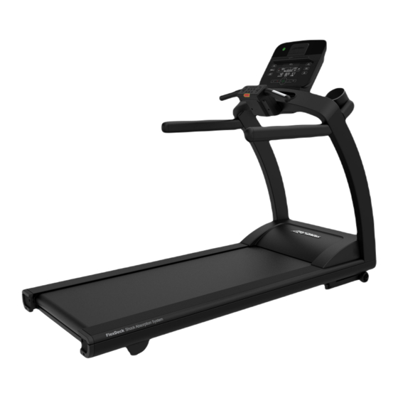
3. Product Overview Index Item Description Qty. Handlebar Emergency Stop Lanyard Contact Heart Rate Sensors Activity Zone Cup Holder USB Port Console Upright Assembly Rear Roller Adjustment Bolt Walking Belt Side Rail On/Off Switch Power Cord Emergency Stop The treadmill is equipped with an Emergency Stop System. The system consists of a rectangular stop magnet (located on the upper bridge plastic) attached to a safety stop pull cord. -
Page 11: Mounting And Dismounting Treadmill
safety stop pull cord removed no keys shall function on the treadmill. Place the safety stop pull cord back in place. The treadmill will reset and will be ready for operation. Mounting and Dismounting Treadmill Use the handrails to enhance stability when mounting or dismounting a treadmill. Never mount or dismount the treadmill while the running belt is moving. -
Page 12: Assembly Procedure
4. Assembly Procedure Components Item Description Console Bridge Cover Accessory Tray Bridge Assembly Safety Key Left Upright Assembly Right Upright Assembly Cupholder Insert Deck Assembly Hardware Kit Hardware Item Description M10 X 25mm Hex Head Screw M10 Star Washer #10 X 1/2 Phillips Pan Head Screw #6 X 3/8 Phillips Pan Head Screw Page 10 of 31... -
Page 13: Required Tools
Required Tools Item Description Size 17mm Wrench 1/2" 17mm Socket 1/2" Torque Wrench Hex Wrench Rubber Mallet Safety Glasses Removing Motor Cover 1. Remove screws securing motor cover. NOTE: Do not yet attempt to remove shipping pallet. Item Description Motor Cover 10-16 X 8 Phillips Screw Shipping Pallet Page 11 of 31... - Page 14 2. Carefully tilt motor cover upward. Item Description Motor Cover 3. Lift and remove motor cover from unit. Item Description Motor Cover Page 12 of 31...
- Page 15 4. Remove hardware and detach deck assembly from shipping pallet. Discard of hardware and shipping pallet. Item Description 5/16-9 X 2-1/2 Lag Bolt 5/16" ID Washer Deck Assembly Shipping Pallet Page 13 of 31...
-
Page 16: Attach Uprights
Attach Uprights 1. Attach left and right upright assemblies. Tighten to 17.5 Nm (12.9 ft-lbs.). NOTE: Be careful not to pinch cables extending out of right upright assembly. Item Description Qty. Left Upright Assembly M10 x 25mm Hex Bolt Lock Washer Right Upright Assembly 2. -
Page 17: Attach Bridge And Console
Attach Bridge and Console 1. Attach bridge assembly to uprights and tighten to 17.5 Nm (12.9 ft-lbs.). NOTE: Be careful not to pinch right upright cables. Item Description 10 x 25mm Hex Bolt Lock Washer Bridge Assembly Left Upright Assembly Right Upright Assembly Right Upright Cable 2. - Page 18 3. Remove screws from bridge and reuse to attach console. Tighten to 17.5 Nm (12.9 ft-lbs.). Item Description 10 x 25mm Socket Head Screw Console 4. Attach cables to console. Tuck any excess cable inside console. Item Description Console Cables Page 16 of 31...
- Page 19 5. Attach bridge cover. Tighten to 4 Nm (3 ft-lbs.). Item Description #10 x 1/2 Phillips Screw Bridge Cover 6. Insert cup holders and accessory tray. Item Description Cup Holder Accessory Tray Page 17 of 31...
-
Page 20: Attach Motor Cover
7. Place magnetic end of safety key into bridge assembly. Item Description Bridge Assembly Safety Key Attach Motor Cover 1. Carefully tilt motor cover into position, assuring the rear clips are engaged. Item Description Motor Cover Page 18 of 31... -
Page 21: Calibration
“FAIL”. If a failure occurred press STOP twice and restart the process at Step 1. If failure occurs again take note of the error number display and contact Life Fitness Customer Support Services. 9. Upon successful completion press the RESET key three times to exit calibration mode. -
Page 22: Activity Zone
Activity Zone 1. Start: Causes the belt to begin moving at 0.5 mph and 0% elevation. 2. Stop: Causes the belt to slow to a gradual stop. One push pauses the workout, two pushes displays workout information, and three pushes reset the workout. 3. -
Page 23: Heart Rate Sensors
Heart Rate Sensors Item Description Heart Rate Sensor The heart rate sensors are the built-in heart rate monitoring system on the treadmill. During a workout, grasp the sensors that are attached to the activity zone. For an accurate reading, use a comfortable grip. The console displays the heart rate after 15 to 20 seconds. -
Page 24: Service And Technical Data
5. Service and Technical Data Preventive Maintenance Tips NOTE: Safety of the equipment can be maintained only if the equipment is examined regularly for damage or wear. Keep the equipment out of use until defective parts are repaired or replaced. Pay special attention to parts that are subject to wear, as outlined below. -
Page 25: Troubleshooting Treadmill
Using a voltmeter, verify power at outlet. If no power exists, reset circuit breaker at panel. Line cord is damaged. Replace line cord. Contact Life Fitness Customer Support. Line cord is improperly seated in socket. Inspect power connections at wall outlet and at machine for proper contact. - Page 26 • Incorrect console or power supply. • Line cord at treadmill • Power switch • All console connections • All lower electronics connections Contact Life Fitness Customer Support. Unit resets randomly or pauses. Probable Cause Corrective Action Power source is insufficient.
-
Page 27: Troubleshooting The Polar ® Heart Rate Chest
Troubleshooting the Polar ® Heart Rate Chest Strap Heart rate reading is erratic or absent entirely Probable Cause Corrective Action Belt transmitter electrodes are not wet enough to pick up Wet the belt transmitter electrodes. accurate heart rate readings. Belt transmitter electrodes are not laying flat against the Ensure the belt transmitter electrodes are laying flat skin. - Page 28 Free area Item Distance 6.5 ft. (2.0m) 1.64 ft. (0.5m) After placing the unit where it will be used, check its stability. If there is even a slight rocking motion or the unit is not stable, determine which stabilizing leg is not resting on the floor. To adjust, loosen the Jam Nut, and turn the Stabilizing Leg until the rocking motion ceases, and both stabilizing legs rest firmly on the floor.
- Page 29 Belt Tensioning A 6mm hex key wrench is required for this task. The treadmill has access holes in the rear roller guards which allow access to the tensioning bolts. These tensioning bolts make it possible to adjust the tracking and centering of the striding belt without removing the guards.
- Page 30 NOTE: Do not exceed one full turn of the adjusting screws in either direction. If after one full turn the belt does not track properly, contact Life Fitness Customer Support. Do not overtighten the tensioning bolts while making belt adjustments. Overtightening of bolts may over stretch and damage the striding belt or roller.
-
Page 31: Specifications
6. Specifications Specifications Designed Use Home EN ISO 20957 Class H Maximum User Weight 400 lbs. / 181 kg Speed Range 0.5 - 12.0 MPH (0.8 - 19 KPH) in 0.1 increments Elevation Range 0% - 15% (in 0.5% increments) Drive Train DC motor with variable speed controller Motor Size... -
Page 32: Safety Product Registration
Who Pays Shipping and Insurance for Service If the Product or any warranted part must be returned to a service facility for repairs, Life Fitness will pay all shipping and insurance charges during the warranty period (within the United States only). The purchaser is responsible for shipping and insurance charges after the warranty has expired. -
Page 33: Exclusive Warranty
Warranty coverages and terms may differ outside the United States. Please contact the Life Fitness office servicing your country (contact information found at the front of this manual) or visit the applicable local Life Fitness website to receive the specific warranty information for your country.
Need help?
Do you have a question about the Run CX and is the answer not in the manual?
Questions and answers