Table of Contents
Advertisement
Quick Links
Table of Contents
2017-03-22
Operating manual
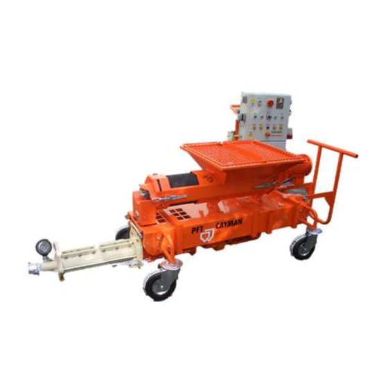
CAYMAN
Part 2 Overview – Operation - Spare parts lists
Article number of the operating manual: 00 59 79 01
Article number of the parts list-machine: 00 24 88 94 CAYMAN with frequency converter
Article number of the parts list-machine: 00 44 33 71 CAYMAN without frequency converter
Read the operating manual prior to starting any work!
Advertisement
Table of Contents

Related Manuals for PFT CAYMAN


Summary of Contents for PFT CAYMAN
- Page 1 Part 2 Overview – Operation - Spare parts lists Article number of the operating manual: 00 59 79 01 Article number of the parts list-machine: 00 24 88 94 CAYMAN with frequency converter Article number of the parts list-machine: 00 44 33 71 CAYMAN without frequency converter...
- Page 2 © Knauf PFT GmbH & Co. KG P.O. Box no. 60 97343 Iphofen Einersheimer Straße 53 97346 Iphofen Germany Phone +49 9323 31-760 Fax +49 9323 31-770 Technical hotline +49 9323 31-1818 info@pft.net www.pft.net 2017-03-22...
-
Page 3: Table Of Contents
CAYMAN Part 2 Overview – Operation - Spare parts lists Table of Contents 12.1 Scope of application booster pump ..20 EC Declaration of Conformity ..... 6 12.2 Intended use ........20 Examination ..........7 13 Work flow ............ 21 Examination by machine operator .. - Page 4 CAYMAN Part 2 Overview – Operation - Spare parts lists Table of Contents 24 Hazardous dusts ........33 36 Rest ............. 45 25 Feeding dry material to the machine ..33 37 End of work / clean machine ....46 37.1 Secure against restarting ....
- Page 5 CAYMAN Part 2 Overview – Operation - Spare parts lists Table of Contents 44.6 Spare parts drawing CADDY with 44.12 Control cabinet article water tap assembly ......68 number 00280799 ......80 44.7 Control cabinet with FU Article 45 Circuit diagrams ......... 82 number 00250808 ......
-
Page 6: Ec Declaration Of Conformity
Person authorised to compile the relevant technical documentation: Dipl.-Wirtsch.-Ing. (FH) Michael Duelli, Einersheimer Straße 53, 97346 Iphofen. The technical documentation is available from: Knauf PFT GmbH & Co. KG, Technical Department, Einersheimer Straße 53, 97346 Iphofen. Iphofen, Dr. York Falkenberg... -
Page 7: Examination
CAYMAN Part 2 Overview – Operation - Spare parts lists Examination 2 Examination 2.1 Examination by machine operator Prior to each shift, the machine operator has to examine the effectiveness of the control and safety devices as well as the proper fitting of the protection devices. -
Page 8: General Information
CAYMAN Part 2 Overview – Operation - Spare parts lists General information 3 General information 3.1 Information regarding the operating manual This operating manual gives important information on handling the device. A prerequisite for safe working is the observance of all stated safety guidelines and instructions. -
Page 9: Spare Parts Lists
(in the business login) at www.pft.eu. 5 Periodic inspections Inspection recommendations for the annual expert inspection of the CAYMAN (which is to be conducted in accordance with BGR 183) can be found in this section. -
Page 10: Technical Data
CAYMAN Part 2 Overview – Operation - Spare parts lists Technical data 6 Technical data 6.1 General information CAYMAN Detail Value Unit 6.2 Power connection Cmpl. weight 435 kg Weight mixer / chassis approx. 195 kg Weight pump approx. 140 Kg Weight caddy approx. -
Page 11: Operating Conditions
CAYMAN Part 2 Overview – Operation - Spare parts lists Technical data Water connection Detail Value Unit Water pressure in running machine Water connection inch Fig. 2: Water connection 6.3 Operating conditions Environment Detail Value Unit Temperature range 2-45 °C Relative humidity, max. -
Page 12: Dimension Sheet
CAYMAN Part 2 Overview – Operation - Spare parts lists Dimension sheet 7 Dimension sheet 1900/2615 Fig. 3: Dimension sheet 7.1 Name plate The type plate is located in the mixing tube and in the CADDY and includes the following information:... -
Page 13: Overview Cayman
CAYMAN Part 2 Overview – Operation - Spare parts lists Overview CAYMAN 8 Overview CAYMAN Fig. 5: Table of the assembly groups 1. Mortar outlet flange in mixer 8. Castor 2. Rubber mixing tube 9. Undercarriage 3. Protective grille with sack opener 10. -
Page 14: Description Of Assemblies
CAYMAN Part 2 Overview – Operation - Spare parts lists Description of assemblies 9 Description of assemblies 9.1 Overview of the control box with FU Article number 00250808 1. Dummy connector / Connection for remote control cable. 2. Connection wet sensor (wet sensor in pump material container). -
Page 15: Overview Of Control Box Article Number 00280799
CAYMAN Part 2 Overview – Operation - Spare parts lists Description of assemblies 9.2 Overview of control box article number 00280799 1. Push button for control voltage “ON/ OFF”. 2. Main reversing switch = emergency-stop switch 3. Control lamp machine ready for operation. -
Page 16: Overview Of Water Tap Assembly
CAYMAN Part 2 Overview – Operation - Spare parts lists Description of assemblies 9.3 Overview of Water tap assembly Fig. 8: Water tap assembly 1. Booster pump. 7. Pressure switch for water. 2. Pre-filter with tray. 8. Needle valve to regulate the water quantity. -
Page 17: Operating Modes
CAYMAN Part 2 Overview – Operation - Spare parts lists Operating modes 10 Operating modes 10.1 Selector switch for operating modes Main switch “ON”, control voltage “ON”, Selector switch position “0”,: Machine is ready for operation, green control lamp lights up. -
Page 18: Intended Use Control Panel
CAYMAN Part 2 Overview – Operation - Spare parts lists Intended use control panel Main switch “ON”, control voltage “ON”, Selector switch pump “Manual”: Pump motor is in operation. Pump motor is operated separately to empty the pump motor container. -
Page 19: Intended Purpose Control Panel
CAYMAN Part 2 Overview – Operation - Spare parts lists Intended use control panel 11.2 Intended purpose control panel The tool is conceptualised and designed exclusively for the purpose of use specified here. Scope of application: Primary use for water and neutral, non-adhesive liquids. Also suitable for air and neutral non-flammable gases. -
Page 20: Description Booster Pump
CAYMAN Part 2 Overview – Operation - Spare parts lists Description Booster pump 12 Description Booster pump 12.1 Scope of application booster pump The PFT booster pump is mainly used as booster pump for interposing at the mortar mixer and mortar mixing pumps with insufficient water pressure. -
Page 21: Work Flow
Adhere to the usage directives of the material manufacturer. The machine combination PFT CAYMAN can be loaded with material in sacks or via delivery hood under a Silo / Container with material. The material reaches in the pump container of the delivery pump by a horizontal mixer equipped with its own drive after addition of water in mixing tube and is forwarded from there at up to 100 l/min to processing plant. -
Page 22: Material
CAYMAN Part 2 Overview – Operation - Spare parts lists Material: 15 Material: 15.1 Flowability / Flow characteristic NOTE! The pump unit can be used up to 25 bar operating pressure. The possible conveying distance depends mainly on the flowability of the material. -
Page 23: Transport, Packing And Storage
CAYMAN Part 2 Overview – Operation - Spare parts lists Transport, packing and storage 18 Transport, packing and storage 18.1 Safety instruction for transport Improper transport ATTENTION! Damage from improper transport! Improper transport cause substantial property damage. Therefore: When unloading the packages on delivery as well as transport within the company pay attention and observe the symbols and instruction on the package. -
Page 24: Transport Inspection
CAYMAN Part 2 Overview – Operation - Spare parts lists Transport, packing and storage 18.3 Transport inspection On receipt check the delivery immediately for completeness and transport damage. In case of externally visible transport damage, proceed as follows: Do not accept the delivery or under reserve only. -
Page 25: Transport By Car Or Truck
CAYMAN Part 2 Overview – Operation - Spare parts lists Packaging 18.5 Transport by car or truck DANGER! Danger of injury by unsecured loads! In case of road transport, all persons involved in the loading process are responsible for the proper securing of the load. -
Page 26: Operation
CAYMAN Part 2 Overview – Operation - Spare parts lists Operation Handling packaging materials ATTENTION! Environmental damage due to wrong disposal! Packaging materials are valuable raw materials and in many cases they can be reused or reconditioned and recycled. Therefore: –... -
Page 27: Machine Preparation
Never reach into the running machine. Fig. 20: Risk of injury Put up the PFT CAYMAN on a stable, even surface and secure against unwanted movements: Put up the machine in such a way that it cannot be hit by falling objects. -
Page 28: Connection Of The Machine Fu 00248894 To The Power Supply
CAYMAN Part 2 Overview – Operation - Spare parts lists Machine preparation 21.3 Connection of the machine FU 00248894 to the power supply 1. Connect the machine to the site distribution board 400 V only. DANGER! Danger of death from electric current! -
Page 29: Connection Of The Machine 00443371 To The Power Supply
CAYMAN Part 2 Overview – Operation - Spare parts lists Machine preparation 21.5 Connection of the machine 00443371 to the power supply 1. Connect the machine to the site distribution board 400 V only. DANGER! Danger of death from electric current! -
Page 30: Connecting The Water Supply
CAYMAN Part 2 Overview – Operation - Spare parts lists Machine preparation 21.7 Connecting the water supply 1. Connect to water supply with 3/4” hose. 2. The water supply line must first be rinsed to vent the hose line and to clean it of contaminations. -
Page 31: Switching On
CAYMAN Part 2 Overview – Operation - Spare parts lists Switching on 22 Switching on 22.1 Main switch Set the main reversing switch (1) to ‘I’. 1. If the yellow pilot lamp “Change direction of rotation” lights up, the direction of rotation at the main switch must be changed. -
Page 32: Mortar Pressure Gauge
CAYMAN Part 2 Overview – Operation - Spare parts lists Mortar pressure gauge NOTE! Before switching over from step switch to other “ON” operating modes, the control voltage must be switched off through the push button operation “ON / “OFF”... -
Page 33: Hazardous Dusts
CAYMAN Part 2 Overview – Operation - Spare parts lists Hazardous dusts 24 Hazardous dusts Warning! Health hazard caused by dust! In the long term, inhaled dust can lead to lung damage or have other adverse health effects. NOTE! The machine operator or the person working in the dusty area always have to wear a dust protection mask when Fig. -
Page 34: Connect Mortar Hose
CAYMAN Part 2 Overview – Operation - Spare parts lists Putting the machine into operation 27.2 Connect mortar hose 1. Smear the mortar hose with approximately two litres of lime sludge to avoid clogging of hose. 2. Connect mortar hose (1) to the pressure flange (2). -
Page 35: Potentiometer
CAYMAN Part 2 Overview – Operation - Spare parts lists Potentiometer 28 Potentiometer 28.1 Litre output of pump 1. The litre output of the pump can be controlled via the potentiometer. Fig. 48: Potentiometer 2. The higher the potentiometer is turned, the higher the motor speed of the pump motor and this also the litre output of the pump (apparent from the adjacent table). -
Page 36: Wet Sensor
CAYMAN Part 2 Overview – Operation - Spare parts lists Remote control 29.2 Wet sensor 1. The material level in the material container of the pump container is monitored by a wet sensor (1). 2. Sensor rod short (2), level maximum. -
Page 37: Stopping In Case Of An Emergency
CAYMAN Part 2 Overview – Operation - Spare parts lists Stopping in case of an emergency 32 Stopping in case of an emergency In dangerous situation machine movements have to be stopped as Stopping in case of an emergency quickly as possible, and the power supply has to be disconnected. -
Page 38: Work On Troubleshooting
CAYMAN Part 2 Overview – Operation - Spare parts lists Work on troubleshooting 34 Work on troubleshooting 34.1 Reaction in the event of faults The following strictly applies: 1. In the event of faults presenting immediate danger to persons or property, activate the EMERGENCY-STOP function immediately. -
Page 39: Lamp Test
CAYMAN Part 2 Overview – Operation - Spare parts lists Work on troubleshooting 34.3 Lamp test NOTE! Please press the push button “lamp test” (1) at least once per shift to check the function of the signal lamps. Faulty operation of the system can thus be Fig. -
Page 40: Table Of Faults
CAYMAN Part 2 Overview – Operation - Spare parts lists Work on troubleshooting 34.6 Table of faults Fault Possible cause Solution Rectification by Machine does No water Pressure switch or solenoid valve Service engineer not start: defective Water Water pressure too low - pressure... - Page 41 CAYMAN Part 2 Overview – Operation - Spare parts lists Work on troubleshooting Fault Possible cause Solution Rectification by Remote control Plug of the remote control cable Operator Check the proper fit of the plug not inserted properly. Repair or replace remote control...
- Page 42 CAYMAN Part 2 Overview – Operation - Spare parts lists Work on troubleshooting Fault Possible cause Solution Rectification by meter does not Solenoid coil defective Change solenoid coil Service engineer display water Pressure reducing valve closed Open pressure reducing valve Operator quantity.
-
Page 43: Transport Is At A Standstill / Blockage
CAYMAN Part 2 Overview – Operation - Spare parts lists Transport is at a standstill / Blockage 35 Transport is at a standstill / Blockage Clogging might form in the feed hoses for several reasons. This means that the material to be conveyed remains stuck in the feed hoses and cannot be pumped to the hose end. -
Page 44: Danger When There Is Overpressure In Mortar Hose
CAYMAN Part 2 Overview – Operation - Spare parts lists Transport is at a standstill / Blockage 35.4 Danger when there is overpressure in mortar hose DANGER! Danger from discharged material! Never loosen the hose couplings as long as the pressure head is reduced! Material to be conveyed can be discharged under pressure and cause injuries particularly to the eyes. -
Page 45: Blockage Cannot Be Cleared
CAYMAN Part 2 Overview – Operation - Spare parts lists Rest 35.6 Blockage cannot be cleared NOTE! Mortar hoses are cleaned immediately. 1. Cover coupling connections with tear-proof film. 2. Loosen cam leaver and hose connections. 3. Dislodge the blockage by tapping or shaking at the place where the blockage is located. -
Page 46: End Of Work / Clean Machine
CAYMAN Part 2 Overview – Operation - Spare parts lists End of work / clean machine 37 End of work / clean machine 37.1 Secure against restarting DANGER! Danger to life from unauthorised restarting! When working with the machine there is the risk that the energy supply is switched on without authorisation. -
Page 47: Cleaning The Mortar Hoses
CAYMAN Part 2 Overview – Operation - Spare parts lists End of work / clean machine 37.4 Cleaning the mortar hoses NOTE! The mortar hoses must be cleaned immediately. 1. Press the water saturated sponge ball (1) into the mortar hose (2). -
Page 48: Cleaning The Pump And Pump Container
CAYMAN Part 2 Overview – Operation - Spare parts lists End of work / clean machine NOTE! Do not clean dry section (5) with water. Keep the dry section (5) free of caking. Fig. 68: Dry section 37.6 Cleaning the pump and pump container 1. -
Page 49: Installing The Cleaned Mixing Tube
CAYMAN Part 2 Overview – Operation - Spare parts lists Action in case of power cut 9. Turn the selector switch to position “3” (Manual pump) ( Fig. 72) 10. Pump the water from the pump container till clean water come out at the mortar hose connection. -
Page 50: Measures To Be Taken In Case Of Water Outage
CAYMAN Part 2 Overview – Operation - Spare parts lists Measures to be taken in case of water outage 39 Measures to be taken in case of water outage NOTE! Water can be supplied to the machine from a container by means of suction strainer (article number 00 13 66 19). -
Page 51: Maintenance
CAYMAN Part 2 Overview – Operation - Spare parts lists Maintenance 9. Turn the selector switch to position “3” (Manual pump) ( Fig. 80) 10. Briefly switch the machine on by pressing the green push button control voltage “ON” ( so that the residual water is Fig. -
Page 52: Adjust Clamping Of Pump
Thorough cleaning of the machine is the most important maintenance. 41.1 Adjust clamping of pump 1. The CAYMAN is equipped with a pump system that can be retightened. 2. If the pumping pressure decreases, the stator can be adjusted. -
Page 53: Safety
CAYMAN Part 2 Overview – Operation - Spare parts lists Maintenance 41.3 Safety Personnel The maintenance works described here can be carried out by the operator, unless marked otherwise. Some maintenance work must only be carried out by specially trained technical personnel or exclusively by the manufacturer. -
Page 54: Cleaning
CAYMAN Part 2 Overview – Operation - Spare parts lists Maintenance 41.4 Cleaning The inside of the hopper can be cleaned with a water hose after having been emptied completely. ATTENTION! Water can enter sensitive machine parts! Before cleaning the machine cover all openings in which no water must enter for safety and functional reasons (e.g.: electric motors and... -
Page 55: Seal Unit
CAYMAN Part 2 Overview – Operation - Spare parts lists Maintenance Grease quick closures and turning bolts. Fig. 86: Lubrication 41.7 Seal unit Weekly check at the inspection glass of the seal unit. Top up seal unit with commercially available gear grease. -
Page 56: Actions After Completed Maintenance
CAYMAN Part 2 Overview – Operation - Spare parts lists Disassembly 41.9 Actions after completed maintenance After finishing the maintenance works and prior to switching on the machine, the following steps have to be carried out: Check all previously loosened screw connections for secure fit. -
Page 57: Disassembly
CAYMAN Part 2 Overview – Operation - Spare parts lists Disposal Electrical system DANGER! Danger of death from electric current! There is danger to life if you come in contact with live parts. Activated electrical components can carry out uncontrolled movements and cause serious injuries. -
Page 58: Spare Parts Drawing / Spare Parts List
CAYMAN Part 2 Overview – Operation - Spare parts lists Spare parts drawing / spare parts list 44 Spare parts drawing / spare parts list 44.1 Pump motor / pump container 2017-03-22... - Page 59 CAYMAN Part 2 Overview – Operation - Spare parts lists Spare parts drawing / spare parts list Pos. Quantity Art. no. Name 20 14 35 01 Gear motor 7.5 kW, 175 rpm 00 07 03 57 Motor connection cable 4 x 2.5 mm², 16 A, 10-pin - 5 m 00 06 69 81 EMC cable gland M25 x 1.5...
-
Page 60: Pump Unit
CAYMAN Part 2 Overview – Operation - Spare parts lists Spare parts drawing / spare parts list 44.2 Pump unit 2017-03-22... - Page 61 CAYMAN Part 2 Overview – Operation - Spare parts lists Spare parts drawing / spare parts list Pos. Quantity Art. no. Name 20 20 85 22 Splint bolt 8 H11 x 58 x 54 with washer und splint, galvanised 20 10 08 01...
-
Page 62: Gear Motor 4 Kw, 273 Rpm Complete, Article No. 00097094
CAYMAN Part 2 Overview – Operation - Spare parts lists Spare parts drawing / spare parts list 44.3 Gear motor 4 kW, 273 rpm complete, article no. 00097094 2017-03-22... - Page 63 CAYMAN Part 2 Overview – Operation - Spare parts lists Spare parts drawing / spare parts list Pos. Quantity Art. no. Name 00 09 70 94 Drive HM 2006, 4 kW, 273 rpm, complete 00 05 36 03 Gear motor 4 kW, 273 rpm 20 42 41 36 Motor connection cable 5.0 m CEE 4 x 16A...
-
Page 64: Material Container With Rubber Mixing Tube
CAYMAN Part 2 Overview – Operation - Spare parts lists Spare parts drawing / spare parts list 44.4 Material container with rubber mixing tube. 2017-03-22... - Page 65 CAYMAN Part 2 Overview – Operation - Spare parts lists Spare parts drawing / spare parts list Pos. Quantity Art. no. Name 00 17 38 26 Protective grille 20 20 87 01 Hex. screw M8 x 16 galvanised 20 20 93 13 Washer B 8.4, galvanised...
-
Page 66: Cayman Undercarriage
CAYMAN Part 2 Overview – Operation - Spare parts lists Spare parts drawing / spare parts list 44.5 CAYMAN undercarriage 2017-03-22... - Page 67 CAYMAN Part 2 Overview – Operation - Spare parts lists Spare parts drawing / spare parts list Pos. Quantity Art. no. Name 00 00 21 87 CAYMAN stop axel 20 10 10 10 Lynch pin D 4.5 with ring 20 20 66 03 Safety capped nut M8, galvanised 20 20 93 13 Washer B 8.4, galvanised (PACKING UNIT = 10 PCS)
-
Page 68: Spare Parts Drawing Caddy With Water Tap Assembly
CAYMAN Part 2 Overview – Operation - Spare parts lists Spare parts drawing / spare parts list 44.6 Spare parts drawing CADDY with water tap assembly 2017-03-22... - Page 69 CAYMAN Part 2 Overview – Operation - Spare parts lists Spare parts drawing / spare parts list 44.6.1 Spare parts list Caddy with water tap assembly Pos. Quantity Art. no. Name 00 58 11 67 CADDY CAYMAN BETA II undercarriage 00 15 13 82 Booster pump 1.1 KW 400 V 50 Hz...
-
Page 70: Control Cabinet With Fu Article Number 00250808
CAYMAN Part 2 Overview – Operation - Spare parts lists Spare parts drawing / spare parts list 44.7 Control cabinet with FU Article number 00250808 2017-03-22... - Page 71 CAYMAN Part 2 Overview – Operation - Spare parts lists Spare parts drawing / spare parts list Pos. Quantit Art. no. Name 20 44 45 00 Key for control box 00 03 62 49 Lock for control box (double bit)
-
Page 72: Control Cabinet With Fu Article Number 00250808
CAYMAN Part 2 Overview – Operation - Spare parts lists Spare parts drawing / spare parts list 44.8 Control cabinet with FU Article number 00250808 2017-03-22... - Page 73 CAYMAN Part 2 Overview – Operation - Spare parts lists Spare parts drawing / spare parts list Pos. Quantity Art. no. Name 00 02 21 70 Control transformer 400V-42V/230V 190 VA 20 45 27 15 Evaluation device humidity sensor 00 45 97 35...
-
Page 74: Control Cabinet With Fu Article Number 00250808
CAYMAN Part 2 Overview – Operation - Spare parts lists Spare parts drawing / spare parts list 44.9 Control cabinet with FU Article number 00250808 2017-03-22... - Page 75 CAYMAN Part 2 Overview – Operation - Spare parts lists Spare parts drawing / spare parts list Pos. Quantity Art. no. Name 00 09 11 52 Protective hood of filter fan RAL7035 00 03 63 23 Exit filter for control box...
-
Page 76: Control Cabinet Without Fu Article Number 00280799
CAYMAN Part 2 Overview – Operation - Spare parts lists Spare parts drawing / spare parts list 44.10 Control cabinet without FU Article number 00280799 2017-03-22... - Page 77 CAYMAN Part 2 Overview – Operation - Spare parts lists Spare parts drawing / spare parts list Pos. Quantity Art. no. Name 20452740 Time relay 42 V, 0.5-10 sec. 20 44 81 20 Coupling relay 42 V 2 changer 20 45 27 15...
-
Page 78: Control Cabinet Article Number 00280799
CAYMAN Part 2 Overview – Operation - Spare parts lists Spare parts drawing / spare parts list 44.11 Control cabinet article number 00280799 2017-03-22... - Page 79 CAYMAN Part 2 Overview – Operation - Spare parts lists Spare parts drawing / spare parts list Pos. Quantity Art. no. Name 20 45 52 00 Main switch 00 05 38 73 Indicating lamp insert for green luminous pushbutton 00 18 63 72...
-
Page 80: Control Cabinet Article Number 00280799
CAYMAN Part 2 Overview – Operation - Spare parts lists Spare parts drawing / spare parts list 44.12 Control cabinet article number 00280799 2017-03-22... - Page 81 CAYMAN Part 2 Overview – Operation - Spare parts lists Spare parts drawing / spare parts list Pos. Quantity Art. no. Name 20 42 66 10 CEE socket outlet 4 x 16A 6h, red, small 00 02 20 67 CEE socket outlet 5 x 16A 7h, black...
-
Page 82: Circuit Diagrams
CAYMAN Part 2 Overview – Operation - Spare parts lists Circuit diagrams 45 Circuit diagrams 45.1 Circuit diagrams CAYMAN FU 2017-03-22... - Page 83 CAYMAN Part 2 Overview – Operation - Spare parts lists Circuit diagrams 2017-03-22...
- Page 84 CAYMAN Part 2 Overview – Operation - Spare parts lists Circuit diagrams 2017-03-22...
- Page 85 CAYMAN Part 2 Overview – Operation - Spare parts lists Circuit diagrams 2017-03-22...
- Page 86 CAYMAN Part 2 Overview – Operation - Spare parts lists Circuit diagrams 2017-03-22...
- Page 87 CAYMAN Part 2 Overview – Operation - Spare parts lists Circuit diagrams 2017-03-22...
- Page 88 CAYMAN Part 2 Overview – Operation - Spare parts lists Circuit diagrams 2017-03-22...
- Page 89 CAYMAN Part 2 Overview – Operation - Spare parts lists Circuit diagrams 2017-03-22...
- Page 90 CAYMAN Part 2 Overview – Operation - Spare parts lists Circuit diagrams 2017-03-22...
- Page 91 CAYMAN Part 2 Overview – Operation - Spare parts lists Circuit diagrams 2017-03-22...
-
Page 92: Circuit Diagrams Cayman 400 V
CAYMAN Part 2 Overview – Operation - Spare parts lists Circuit diagrams 45.2 Circuit diagrams CAYMAN 400 V 2017-03-22... - Page 93 CAYMAN Part 2 Overview – Operation - Spare parts lists Circuit diagrams 2017-03-22...
- Page 94 CAYMAN Part 2 Overview – Operation - Spare parts lists Circuit diagrams 2017-03-22...
- Page 95 CAYMAN Part 2 Overview – Operation - Spare parts lists Circuit diagrams 2017-03-22...
-
Page 96: Index
CAYMAN Part 2 Overview – Operation - Spare parts lists Index 46 Index Disconnect the mortar hoses ..........46 Action in case of power cut ..........49 Disposal ..............57 Actions after completed maintenance ........56 Dry-sensor ..............35 Adjust clamping of pump ..........52 Automatic mode ............ - Page 97 CAYMAN Part 2 Overview – Operation - Spare parts lists Index Power connection ............10 Machine preparation ............27 Power values ...............11 Main switch ..............31 Pre-filter ..............55 Maintenance ............... 51 Pre-setting the water flow rate ..........31 Maintenance plan ............54 Pull pump unit from chassis ..........27...
- Page 98 CAYMAN Part 2 Overview – Operation - Spare parts lists Index Transport ............23, 24 Transport by car or truck ..........25 Water inlet filter ............55 Transport inspection ............24 Wet sensor ..............36 Transport is at a standstill / Blockage ........43 Work flow ..............
- Page 99 CAYMAN Part 2 Overview – Operation - Spare parts lists 2017-03-22...
- Page 100 CAYMAN Part 2 Overview – Operation - Spare parts lists PFT – THE FLOW OF PRODUCTIVITY Knauf PFT GmbH & Co. KG P.O. Box no. 60 97343 Iphofen Einersheimer Straße 53 97346 Iphofen Germany Phone +49 9323 31-760 Fax +49 9323 31-770 Technical hotline +49 9323 31-1818 info@pft.net...
Need help?
Do you have a question about the CAYMAN and is the answer not in the manual?
Questions and answers