
Related Manuals for Steel City 35-215S3


Summary of Contents for Steel City 35-215S3
- Page 1 owner’s MAnUAL 15’’ PLANER 35-215 For technical support, provide the following model and serial numbers: Model No: ______________________ Serial No: ______________________...
- Page 2 The manufacturer warrants its machines to be free from defects in workmanship and materials for a period of 2 years from the date of the original purchase for Steel City shop machines or for a period of 1 year for Titanium production machines;...
-
Page 3: Table Of Contents
The drawings, illustrations, photographs, and specifications in this user manual represent your machine at time of print. However, changes may be made to your machine or this manual at any time with no obligation to Steel City. ProDUCT sPeCIFICATIons 35-215S3... -
Page 4: Safety
sAFeTY This manual is not totally comprehensive. It does not and can not convey every possible safety and operational problem which may arise while using this machine. The manual will cover many of the basic and specific safety procedures needed in an industrial environment. wArnInG All federal and state laws and any regulations having jurisdiction covering the safety requirements for use of this... - Page 5 22. Do noT operate any machine or tool if under the 4. Prevent electrical shock. Follow all electrical and safety codes, including the National Electrical Code (NEC) and influence of drugs, alcohol, or medication. the Occupational Safety and Health Regulations 23.
-
Page 6: Product Safety
ProDUCT sAFeTY 1. Do not clean the table of chips or dust with hands. Blow 4. Avoid possible reject: do not lower your head down at off with low-pressure air. the level of the cutter head when it is running. 2. -
Page 7: Electrical And Grounding Instructions
eLeCTrICAL AnD GroUnDInG InsTrUCTIons wArnInG IMProPer eLeCTrICAL ConneCTIon equipment-grounding conductor can result in risk of electric To reduce the risk of electric shock, follow all shock. The conductor with the green insulation (with or electrical and safety codes, including the without yellow stripes) is the equipment-grounding National Electric Code (NEC) and the conductor. -
Page 8: Unpacking And Inventory
Check for damaged or missing items as per list below. Please report any damaged or missing part to your steel City dealer immediately. 1. Allen wrench (3, 4, 5 and 6 mm) 2. Combination wrench (8-10 mm, 12-14 mm and 17-19 mm) 3. -
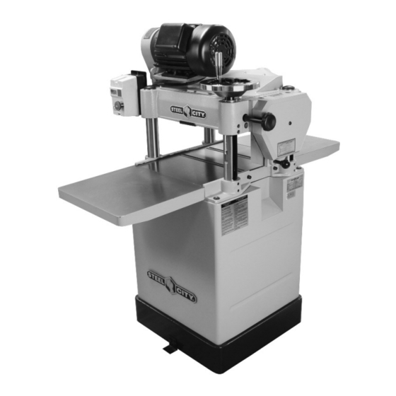
Page 9: Feature Identification
FeATUre IDenTIFICATIon Height adjustment handwheel Magnetic switch Thickness gauge 2 table rollers Cast iron extension tables 2 feed speeds Integrated mobility kit Front view 4” Dust port rear view Page 9... -
Page 10: Assembly
AsseMBLY wArnInG Make sure the switch is in the off position and the machine is unplugged. ◊ InsTALLInG HeIGHT ADjUsTMenT HAnDwHeeL The key, nut and washer are taped onto the handwheel shaft. Carefully remove the tape to get the parts. Insert the handwheel, making sure the keyway is aligned with the key. - Page 11 ◊ InsTALLInG DUsT CHUTe Using the mounting bolts and leveling screws, adjust so that there is no space between the straight edge and Align the dust chute mounting holes with the the tables. corresponding holes in the machine. Attach the dust chute using the mounting bolts and tighten to secure.
-
Page 12: Adjustments
ADjUsTMenTs wArnInG 1. Lay a straight edge across both rollers, loosen the set Make sure the switch is in the off position and screws. the machine is unplugged. noTe: Your planer was carefully adjusted at the factory. However any inaccuracies due to rough handling in transit can easily be corrected by following these instructions. - Page 13 ◊ CUTTING HEIGHT ◊ FEED SPEED CONTROL Cutting height is adjusted by mean of a handwheel The planer is equipped with a spiral, serrated infeed located on the top right side of the planer infeed. One roller and a smooth solid steel outfeed roller. They turn revolution of the handwheel correspond to a height to feed the stock and they slow automatically when the change of about 4 mm.
- Page 14 ◊ ADjUsTInG DrIVe BeLT TensIon ◊ FEED ROLLER TENSION Drive belt tension should be checked regularly. The feed rollers are under spring tension and the tension must be sufficient to feed stock uniformly CAUTIon through the planer without slipping, but should not be so tight that it causes damage to the board.
- Page 15 ◊ ADJUSTING HEIGHT OFFSET The following diagram shows the height offset between the BETWEEN CUTTER HEAD, cutter head and the other components inside the headstock of the planer. Adjustments are below the lowest point of the CHIPBREAKER AND FEED ROLLERS cutter head and were made at the factory.
- Page 16 ◊ DUsT CoLLeCTIon 4. Raise the headstock, place the dial indicator, or the gauge block with a feeler gauge of 0.020” on top of wArnInG gauge block. 5. Lower the cutter head until the lowest point of the Using this machine without dust collection may cutter head (knife) barely touches the dial indicator and cause premature wear, but also represent health zero it, or until it barely touches the feeler gauge on the...
-
Page 17: Maintenance
MAInTenAnCe MEMBER INTERVAL LUBRICANT Chain Frequently Grease First at 20 hours, HD-100, Mobil gear 627, Shell Omala 100, Gear box then each 2500 hours Esso Spartan EP-100 (once a year) Rollers Frequently SAE-30 oil Worm gear Frequently Grease Lead screw Frequently Grease Column... - Page 18 ◊ AnTI-KICKBACK FInGers InsPeCTIon 1. This planer is equipped with anti-kickback fingers. Once engaged, the workpiece can only move towards the cutter head. This prevents accidental kickbacks which can cause serious injuries. Anti-Kickback Fingers workpiece Anti-Kickback Fingers Inspect the anti-kickback fingers regularly to ensure they can move freely, and that their teeth are clean and are sharp enough to stop a board from moving backwards.
-
Page 19: Parts List
PArTs LIsT 35-215s3 Page 19... - Page 20 35-215s3 Page 20...
- Page 21 35-215s3 Page 21...
- Page 22 35-215s3 Page 22...
- Page 23 35-215s3 Page 23...
- Page 24 35-215s3 Page 24...
Need help?
Do you have a question about the 35-215S3 and is the answer not in the manual?
Questions and answers