
Related Manuals for Steel City 40285


Summary of Contents for Steel City 40285
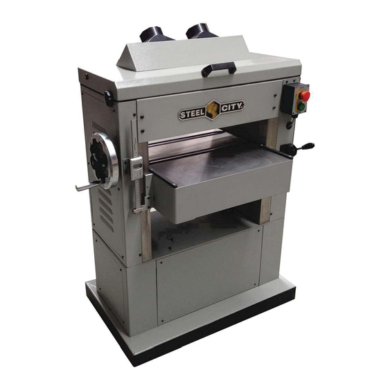
- Page 1 ® User Manual Read and understand this manual before using machine. 20” HEAVY DUTY PLANER Model Number 40285 40285H STEEL CITY TOOL WORKS VER. 11.19.13...
-
Page 3: Table Of Contents
Steel City Tool Works strongly recommends that this product NOT be modified and/or used for any application other than for which it was designed. If you have any questions relative to its application DO NOT use the product until you have contacted Steel City Tool Works and we have advised you. Contact us online at www.steelcitytoolworks.com... -
Page 4: General Safety Rules
GENERAL SAFETY RULES WARNING: Failure to follow these rules may result in serious personal injury. For your own safety, read the instruction manual Use the proper extension cord. Make sure your before operating the machine. Learning the machine’s extension cord is in good condition. When using an application, limitations, and specific hazards will greatly extension cord, be sure to use one heavy enough to carry minimize the possibility of accidents and injury. -
Page 5: Additional Specific Safety Rules
ADDITIONAL SPECIFIC SAFETY RULES WARNING: Failure to follow these rules may result in serious personal injury. DO NOT OPERATE THIS MACHINE until it is ALLOW THE CUTTERHEAD TO REACH FULL SPEED completely assembled and installed according to the before feeding a workpiece. Changing speeds while instructions. -
Page 6: Grounding Instructions
GROUNDING INSTRUCTIONS DANGER: This machine must be grounded while in use to protect the operator from electric shock. 1. All grounded, cord-connected machines: In the event of a malfunction or breakdown, grounding provides a path of least resistance for electric current to reduce the risk of electric shock. -
Page 7: Functional Description
FOREWORD The Model 40285 / 40285H is a 20" (508mm) Planer with an adjustable feed rate for optimum planing underload. This machine has cutting capacities of 20" (381mm) width, 6-1/2" (165mm) thick, and 1/8" (5mm) depth of cut. Feed rate is 16/20 FPM. -
Page 8: Unpacking And Cleaning
UNPACKING AND CLEANING Carefully unpack the machine and all loose items from the shipping container(s). Remove the rust preventative oil from unpainted surfaces using a soft cloth moistened with mineral spirits, paint thinner or denatured alcohol. CAUTION: DO NOT use highly volatile solvents such as gasoline, naphtha, acetone or lacquer thinner for cleaning your machine. After cleaning, cover the unpainted surfaces with a good quality household floor past wax. -
Page 9: Product Specification
PRODUCT SPECIFICATIONS Capacities Product Dimensions Maximum stock width 20” / 508mm Footprint 42” x 30” Maximum stock thicknes 8” / 203mm Length 42” Maximum depth-of-cut 1/8” / 3.175mm Width 30” Minimum length of stock 8” / 203mm Height 49” Minimum length of thickness 1/8”... -
Page 10: Identification Of Planing Components
IDENTIFICATION OF PLANING COMPONENTS... -
Page 11: Attaching Handwheel
ATTACHING HANDWHEEL 1. To attach handwheel to elevation shaft Fig.8, remove nut and wash that were used to secure hand wheel shipping. Fig.10 (D). 2. Install knob Fig.7 onto the shaft and tighten to lock Fig.9. Fig.7 Fig.8 Fig.9 Fig.10... -
Page 12: Attaching Top Cover And Dust Parts
ATTACHING TOP COVER AND DUST PARTS 1. To raise the lid, you need to attach the handle (B) Fig.10A with hardware (A) Fig.10A using Allen wrench. 2. Unlock lid, Fig.11 and Fig.12, turning knob (A) clockwise (both sides). 3. Lift lid and engage support bracket (B) Fig.13 / Fig.14 into recess (C) Fig.13 to prevent lid from closing. 4. -
Page 13: Speed Handle Installation
SPEED HANDLE INSTALLATION 1. There are two handles that are the same. Use one for speed change and the other for the roller bed adjustment, Fig.21-22 (A). Insert handle base (B), turn clockwise to tighten. 2. Fig.23 shows how (A&B) interact with (C) to change the speeds at the gearbox location. Fig.21 Fig.22 Fig.23... -
Page 14: Operating Controls And Adjustments
OPERATING CONTROLS AND ADJUSTMENTS HOW TO START AND STOP THE MACHINE 1. The on/off switch is located on the front of the planer. To turn the machine “ON”, push the START button (A) Fig.30. 2. To turn the machine “OFF”, push the STOP button (B) Fig.30. WARNING: Make sure that the switch is in the “OFF”... -
Page 15: How To Control The Feed Speed
HOW TO CONTROL THE FEED SPEED CAUTION: Change speeds only while the motor is running. DO NOT change speeds while planing. Your planer has two feed roll speeds: 16/20fpm and 8/10 per second. The slower feed rate provides more cuts per inch and a finer, smoother finish. -
Page 16: How To Adjust Bed Rollers
HOW TO ADJUST BED ROLLERS Bed rollers, Fig.40 (A) are set close to the table for finishing planing and higher for dimensioning rough stock. To adjust height see Fig.41. Loosen nut (C) and turn bolt (B), you can raise or lower each of the 4 points of contact by repeating 4 times. -
Page 17: How To Check, Adjust And Replace Knives
HOW TO CHECK, ADJUST, AND REPLACE KNIVES WARNING: Wear gloves when you remove the knives for sharpening or replacement. The knives in this planer are very sharp. WARNING: Disconnect the machine from the power source. 1. Fig.44, rotate knob (A) to unlock on both right and left side. Only left side shown. 2. -
Page 18: Inspecting Knives
SETTING/REPLACING KNIVES INSPECTING KNIVES Note: There are also springs in the cutterhead for adjustig knife height. Only one of these options is needed to set the knives—see Step 5 for clarification. Figure 12. Gauge positioned over cutterhead knife. Figure 13. Cutterhead profile diagram. - Page 19 Springs—Push the knife down with the gauge so that the knife edge touches the middle pad of the gauge. Hold the gauge down and tighten the gib bolts just tight enough to hold the knife in place. Repeat Steps 5-7 with the rest of the knives. Note: If this is the first time you are setting the knives, remove the gib and knife from the cutterhead.
- Page 20 TABLE PARALLELISM How to Construct the Gauge Block Use a gauge block to check and adjust height of the chipbreaker and the infeed and outfeed roll. Adjust the cutterhead parallel to the table. Construct a gauge block from hard wood using the dimensions in Fig.
- Page 21 GRAIN...
- Page 22 DISCONNECT THE PLANER FROM POWER! Raise the headstock cover. (Refer to How to Check Knives page) Figure 53. Finding BDC with the Rotacator. Using the cutterhead pulley, rotate the cutterhead so taht the blade on the left edge of the cutterhead is at bottom dead center (BDC) (see Figure 52)—this will also place the knife on the right side of the cutterhead at BDC.
-
Page 23: Adjust Infeed/Outfeed Rollers &Pressure Bar
ADJUST INFEED / OUTFEED ROLLERS & PRESSURE BAR Figure 55. Infeed jam nut and bolt (left side shown). DISCONNECT THE PLANER FROM POWER! 56 + 57. Figure 56. Pressure bar jam nut and bolt (one side shown). - Page 24 Figure 58. Wood blocks on planer table. Figure 57. Outfeed jam nuts and bolt (right side shown). DISCONNECT THE PLANER FROM POWER! cutterhead with the knife at BDC (reference Distances Below Cutterhead at BDC at the beginning of these procedures). gap between the edge of a knife at BDC and the wood blocks.
-
Page 25: Adjust Chipbreaker/Depth Scale
ADJUST CHIPBREAKER ADJUST DEPTH SCALE DISCONNECT THE PLANER FROM POWER! Figure 57). Figure 58. Depth scale pointer. Figure 57. Chipbreaker mounting to headstock casting (right side shown.) -
Page 26: Adjust Table Gibs
ADJUST TABLE GIBS Cap Screws Figure 59. Table gib and way. -
Page 27: Troubleshooting Guide
TROUBLESHOOTING GUIDE This section covers the most common processing problems encountered in planing and what to do about them. Do not make any adjustments until planer is unplugged and moving parts have come to a complete stop. See the section on Wood Characteristics for additional troubleshooting information. - Page 28 Excessive snipe (gouge in the end 1. One or both of the table rollers are 1. Lower the table rollers. of the board that is uneven with the set too high. rest of the cute). 2. Level the outfeed extension wings 2.
-
Page 29: Maintenance With Schedules
MAINTENANCE WITH SCHEDULES SCHEDULE For optimum performance from your machine, follow this maintenance schedule and refer to any specific instructions given in this section. DAILY WEEKLY MONTHLY CHECK. CLEANING after cleaning. REPLACE V-BELTS Fig.60... -
Page 30: Chain Tension
Gearboxes Chains 2 elevation screw bases (found underneath the table and accessed Drain Table Way Figure 10. Gearbox oil drawn/full locations Chain Tension Remove both front and rear access panels. -
Page 31: Table Chain Tension
Table Chain Tension V-Belt Pulley Alignment DISCONNECT THE PLANER FROM POWER! DISCONNECT THE PLANER FROM POWER! Figure 28. Motor mounting fasteners for adjusting V-belt pulley alignment (bottom rear access panel removed). -
Page 32: Outfeed Roller Tension
Outfeed Roller Tension Infeed Roller Tension DISCONNECT THE PLANER FROM POWER! To adjust outfeed roller tension: DISCONNECT THE PLANER FROM POWER! - Page 33 DATE MAINTENANCE PERFORMED REPLACEMENT COMPONENTS REQUIRED...
- Page 34 DATE MAINTENANCE PERFORMED REPLACEMENT COMPONENTS REQUIRED...
- Page 35 ® STEEL CITY TOOL WORKS www.steelcitytoolworks.com 1-877-SC4-TOOL (1-877-724-8665)
Need help?
Do you have a question about the 40285 and is the answer not in the manual?
Questions and answers