
Related Manuals for Steel City 40250


Summary of Contents for Steel City 40250
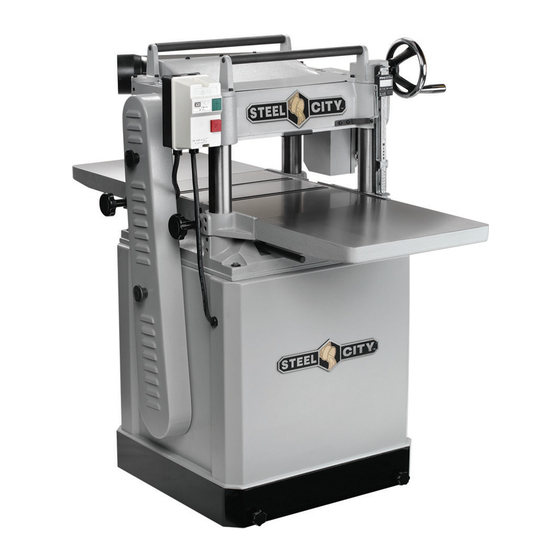
- Page 1 User Manual Read and understand this manual before using machine. 15” PLANER Model No. ® 40250 STEEL CITY TOOL WORKS Manual Part No. OR71029 VER. 3.07...
-
Page 3: Table Of Contents
The drawings, illustrations, photographs, and specifications in this user manual represent your machine at time of print. However, changes may be made to your machine or this manual at any time with no obligation to Steel City Tool Works. -
Page 4: Warranty
2 YEAR LIMITED WARRANTY Steel City Tool Works, LLC (SCTW) warrants this SCTW machinery to be free of defects in workmanship and materials for a period of 2 years from the date of the original retail purchase by the original owner for domestic use. Granite components are warranted for 2 years based on normal use and is void if non SCTW accessories are used that cause the break or chip. -
Page 5: Warranty Card
City:______________________________________________ Online: ______________________________________________ ___ Vacuum Veneer Press ___ Wide Belt Sander Other____________________________________________ How did you first learn of Steel City Tool Works? ___ Advertisement ___ Mail Order Catalog 11. Which benchtop tools do you own? Check all that apply. ___ Web Site... - Page 6 FOLD ON DOTTED LINE PLACE STAMP SteelCityToolWorks #4 Northpoint Court Bolingbrook, IL 60440 FOLD ON DOTTED LINE...
-
Page 7: Product Specifications
3450 ACCESSORIES AND ATTACHMENTS There are a variety of accessories available for your Steel City Product. For more information on any accessories associated with this and other machines, please contact your nearest Steel City distributor, or visit our website at: www.steelcitytoolworks.com. -
Page 8: Feature Identification
FEATURE IDENTIFICATION Switch Dust Port C) Return Rollers D) Table Raise/Lower Handwheel Bed Rollers Table Lock Knobs G) Belt Guard H) Digital Readout... -
Page 9: General Safety
GENERAL SAFETY WARNING WARNING TO AVOID serious injury and damage to the machine, read and follow all Safety and Operating Instructions before assembling and operating this machine. This manual is not totally comprehensive. It does not Exposure to the dust created by power sanding, saw- and can not convey every possible safety and opera- ing, grinding, drilling and other construction activities tional problem which may arise while using this... - Page 10 11. DO NOT FORCE the machine to perform an opera- WARNING tion for which it was not designed. It will do a safer and higher quality job by only performing operations for which the machine was intended. 12. DO NOT stand on a machine. Serious injury could result if it tips over or you accidentally contact any 3.
-
Page 11: Product Safety
9. DO NOT handle the plug or planer with wet hands. 10. USE only accessories as described in this manual. USE accessories only recommended by Steel City. 4. TO REDUCE the risk of electrical shock. DO NOT use this machine outdoors. DO NOT 11. -
Page 12: Electrical Requirements
20. MAKE CERTAIN that the planer is properly adjusted 13. REPLACE a damaged cord immediately. DO NOT prior to use. use a damaged cord or plug. DO NOT use if the planer is not operating properly, or has been dam- 21. -
Page 13: Grounding Instructions
GROUNDING INSTRUCTIONS A machine with a 230 volt plug should only be connect- WARNING ed to an outlet having the same configuration as the plug. EXTENSION CORDS This machine MUST BE GROUNDED while in use to protect the operator from electric shock. WARNING In the event of a malfunction or breakdown, GROUND- ING provides the path of least resistance for electric... -
Page 14: Unpacking & Inventory
“ON” after all the parts have been work surface. obtained and installed correctly. For missing parts, Remove any protective materials and coatings from all contact Steel City at 1-877-SC4-TOOL. of the parts and the planer. The protective coatings can (A) Extension Wings (B) Dust Port... - Page 15 (C) Handwheel (L) 6mm Allen Wrench (D) Handle (M) 5mm Allen Wrench (E) Lock Knobs (N) 4mm Allen Wrench (F) Directional Label (O) 3mm Allen Wrench (G) 10mm Hex Nut (P) M8 x 25mm Hex Head Screws (H) 10mm Flat Washer (Q) M8 x 20mm Set Screws (R) M6 Round Head Screws (J) 12-14mm Open End Wrench...
-
Page 16: Assembly
ASSEMBLY Before beginning assembly, take note of the following Fig. 1 precautions and suggestions CAUTION FLOOR This tool distributes a large amount of weight over a small area. Most commercial floors are appropriate for this unit, however, in residential use, flooring may need added reinforcement to accommodate the weight of the machine and operator. -
Page 17: Extension Wings
HANDWHEEL EXTENSION WINGS The extension wings support the workpiece as it enters The purpose of the handwheel is for raising and lower- and exits the planer. ing the planer table 1. To mount the extension wings, thread three 1. Locate the handwheel shaft at the front right corner M8 x 20mm set screws into the bottom holes of the of the planer. -
Page 18: Dust Port
DUST PORT KNIFE SETTING JIG This planer features a 4-in Dust Port for use with a dust The knife setting jig provides a convenient way to make collection system. If this is planer is not to be hooked up setting the knives quick and simple. to a dust collection system, DO NOT attach the dust port. -
Page 19: Adjustments
ADJUSTMENTS Some of the adjustments covered in this section have 2. Turn the handwheel clockwise to raise the table so already been made at the factory. It is still a good idea that the block barely touches the left side of the to familiarize yourself with all of the following proce- body of the cutterhead. -
Page 20: Chain Tension
5. Referring back to your measurements with the CHAIN TENSION feeler gauge, if the gap difference from one side To adjust Chain Tension: to the other is .004" or less, no adjustment will be necessary. 1. Remove the access panel (A) on the stand. SEE FIG 8A. -
Page 21: Knife Inspection
ADJUSTING CHAIN DRIVE KNIFE INSPECTION Notice: The following steps should only be done CAUTION AFTER you have gone through the TABLE PARALELL- ISM ADJUSTMENT section of this manual and the Planer knives are extremely sharp. Please use extra measurements you attained from that section are caution when your hands are near the blades. -
Page 22: Knife Adjustment
Fig. 10 KNIFE ADJUSTMENT The knives are locked in the cutterhead with wedge type gibs and gib bolts. Springs located under the knives assist in setting the knife height. Jack screws under the knives allow fine tuning to help out in the set- ting process. -
Page 23: Chip Breaker
Fig. 13 4. Rotate the cutterhead until one of the knives are at its lowest point. 5. Using a .040" feeler gauge between the gauge block and the cutterhead, raise the table until the knife just touches the feeler gauge. 6. -
Page 24: Feed Roller Height
FEED ROLLER HEIGHT Fig. 19 The infeed and outfeed rollers are responsible for moving the workpiece through the machine and press- ing the workpiece flat against the main table. WARNING MAKE CERTAIN THE MACHINE IS DISCONNECT- ED FROM THE POWER SOURCE 1. -
Page 25: Chip Deflector
Fig. 20 5. Using a wrench, turn the eccentric shafts to adjust the roller height up or down as shown in FIG 21. Fig. 21 3. Remove the springs that are in the holes left by the set screws and check for any dirt or grit, cleaning off any dirt and replace springs. - Page 26 Fig. 22 WARNING DO NOT apply any oil or other lubricant to the anti- kickback fingers as this can attract dust and restrict the free movement of the fingers. This could result in damage to the planer, the workpiece, or even serious injury to the operator or others in the work area.
- Page 27 BELTS GEAR BOX The gearbox is located just behind the handwheel on WARNING the right side of the planer. The gearbox transfers power from the belt driven cutterhead to the power feed MAKE CERTAIN THE MACHINE IS DISCONNECT- rollers. It has a two speed transmission that is con- ED FROM THE POWER SOURCE trolled by a lever on the right side of the planer.
-
Page 28: Operations
OPERATIONS Fig. 27 WARNING This planer is a very powerful woodworking machine designed and built for professional use. Because of this, the machine should be operated with significant care and caution. Failure to do so could result in severe injury to the operator or others in the work area. -
Page 29: Table Locks
TABLE LOCKS WIXEY ELECTRONIC DIGITAL READOUT Before attempting to adjust the table height, loosen the two black knobs (A) on the left side of the table. Once WARNING the table height is adjusted correctly, retighten the two knobs. SEE FIG 29. MAKE CERTAIN THE MACHINE IS DISCONNECT- Fig. -
Page 30: Maintenance
MAINTENANCE GENERAL GEAR BOX Make a habit of inspecting your planer each time you Gear box oil should be drained after the first 20 hours use it. Check the following conditions and repair or of operation. Replace with 80W-90 gear oil for use in replace as necessary. -
Page 31: Troubleshooting
TROUBLESHOOTING GUIDE This section covers the most common processing problems encountered in planing and what to do about them. Do not make any adjustments until planer is unplugged and moving parts have come to a complete stop. PROBLEM LIKELY CAUSE(S) SOLUTION Motor will not start. - Page 32 (Use only hardwood materials like oak, maple, etc.)
- Page 33 N NOTES N...
-
Page 34: Parts List
PARTS... - Page 35 PART PART DESCRIPTION QTY. DESCRIPTION QTY. OR70405 MOTOR (3HP, 15AMP, 230V, 1PH) OR90311 M8 FLAT WASHER OR70354 MOTOR SPEC PLATE OR90308 M8 x 30mm HEX HEAD SCR OR94006 CAPACITOR OR94008 M8 x 45mm HEX HEAD SCR OR90219 5mm x 5mm x 30mm KEY OR90311 M8 FLAT WASHER OR70936...
- Page 37 PART PART DESCRIPTION QTY. DESCRIPTION QTY. OR70943 EXTENSION WING OR94020 E-RING OR91752 M8 x 25mm HEX HEAD SCREW OR70954 SHAFT OR91821 M8 x 20mm SOC HD SET SCR OR94021 BALL BEARING (6202Z) OR70944 BED ROLLER OR94022 RETAINING RING OR94014 BALL BEARING (608Z) OR70955 CHAIN SPROCKET OR70945...
- Page 39 PART PART DESCRIPTION QTY. DESCRIPTION QTY. OR93372 M6 x 12mm SOC HD CAP SCREW OR70984 HEAD CASTING OR70964 ROLLER BRACKET OR94038 M6 x 16mm HEX HEAD SCREW OR70965 HANDLE OR94039 FLAT WASHER 6.2mm x 22mm x 3mm OR90228 M10 HEX NUT OR70985 OUTFEED ROLLER SPROCKET OR90230...
- Page 41 PART PART DESCRIPTION QTY. DESCRIPTION QTY. OR93975 12MM / 14MM OPEN END WRENCH OR71018 GEAR OR90908 8MM / 10MM OPEN END WRENCH OR92734 BALL BEARING (6201) OR90290 3MM WRENCH OR93936 M6 x 25mm SOC HD CAP SCR OR90291 4MM WRENCH OR71019 GEAR OR91728...
- Page 42 PART PART DESCRIPTION QTY. DESCRIPTION QTY. OR73292 DRO ASSY OR90135 M4 X 6mm ROUND HD SCREW OR73293 BRACKET OR90505 M5 X 12mm ROUND HD SCREW OR73294 ADJUSTABLE PLATE OR90306 M6 X 12mm ROUND HD SCREW OR94798 M5.6 FLAT WASHER OR71029 MANUAL (NOT SHOWN) OR94799 M4.3 FLAT WASHER...
- Page 43 STEEL CITY TOOL WORKS www.steelcitytoolworks.com 1-877-SC4-TOOL (1-877-724-8665) 5 Year Warranty...
Need help?
Do you have a question about the 40250 and is the answer not in the manual?
Questions and answers
Well I finally don't need help finding my part I have found it on the diagram it's number 224 and it's part number 070952 and it's called a column nut I need to know how to quickly order this