Compuprint SP40 User Manual
Compuprint sp40: user guide
Hide thumbs
Also See for SP40:
- User manual (65 pages) ,
- Specifications (2 pages) ,
- User manual (72 pages)
Table of Contents
Advertisement
Quick Links
Download this manual
See also:
User Manual
Advertisement
Table of Contents

Related Manuals for Compuprint SP40


Summary of Contents for Compuprint SP40
- Page 1 Rev. 001...
-
Page 2: Compuprint Products Information
To maintain these printing performances unchanged in the long run, Sferal wwt has developed specific Compuprint branded consumables for each printer type (for example: ribbon cartridges for dot matrix printers, toner and OPC cartridges for laser printers, bubble ink jet cartridges for inkjet printers) that assure an excellent operation with high printing quality level reliability. -
Page 3: Fcc Notes
This equipment has been tested and found to comply with the limits for a Class B digital device, pursuant to Part 15 of the FCC Rules. These limits are designed to provide reasonable protection against harmful interference when the equipment is operated in a commercial environment. -
Page 4: Table Of Contents
Compuprint Products Information ...ii FCC Notes ...iii Canadian D.O.C. Radio Interference Regulationiii EEC Regulations...iii Table of Contents ... iv Printer Presentation ... 1 Unpacking the Printer ... 3 Printer Parts... 4 Printer Installation... 7 Paper Handling ... 14 The Operator Panel ... 16 Software Driver Selection ... -
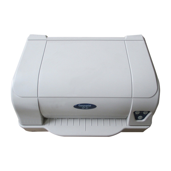
Page 5: Printer Presentation
Easy paper handling The operator places the paper on the front table and the printer loads it without any other user intervention. The paper ejection towards the front or the rear of the printer allows an easy access to the printed document. - Page 6 Standard parallel and serial interface and automatic switch-over function. Easy printer setup through an optically managed menu. Supported emulations: Epson 570, IBM Proprinter XL24E, XL24E AGM, IBM 2390+, 4722, 9068 and Olivetti PR40+, PR2, 2845.
-
Page 7: Unpacking The Printer
Ribbon cartridge Power cable CD-ROM with the printer documentation and drivers. Always keep the packing material in a safe place as you must repack the printer into it, when you Notify any damage to your supplier. need to move it. -
Page 8: Printer Parts
Never remove any printer part unless it is expressly indicated in this manual. P rinter C over O pe ra tor P a ne l P a pe r S tan d P o w er-on P u sh -b utton... - Page 9 Printhead Print H ead Assem bly Print Area Paper Jam R em oval C og-w heel...
- Page 10 P ow er C ab le C o nn ecto r S erial Interfa ce C ab le C on necto r P aralle l Interface C able C onnector...
-
Page 11: Printer Installation
Consider the following points when you choose the location for your printer: The distance between the printer and the host computer must not exceed the length of the interface cable; The location must be sturdy, horizontal and stable; Your printer must not be exposed to direct sunlight, extreme heat, cold, dust or humidity;... - Page 12 1. Find the power cable connector and the rating plate on the rear side of the printer. 2. Insert the power cable into the connector on the printer and the other end into a convenient mains outlet. 3. Press the key on the left side of the printer front to power the printer on.
- Page 13 In order to avoid damaging the print head assembly, this printer accepts only original Compuprint ribbon cartridges. Therefore, if you install a not original cartridge, the printer may not work. 1. Remove the cartridge from its bag. Turn tension knob direction of the arrow to tighten the ribbon.
- Page 14 3. Open the print head assembly pushing the two green levers towards the rear of the printer. The print head assembly moves up. 4. Move the print head to the middle of the print carriage bar.
- Page 15 5. Insert the upper cartridge pins (1) onto the corresponding groove on the print head assembly. Then push the lower pin (2) into the corresponding lower groove until it clicks into place.
- Page 16 6. Insert the ribbon mask onto the print head: match the two grooves (1) on both sides of the ribbon mask with the pins (2) on both sides of the print head. 7. Push the mask up until it clicks into place.
- Page 17 9. Push the print head assembly down, until it clicks into place. If you do not close the print-head assembly correctly, the printer does not print and you may 10. Close the printer cover. damage the printer cover.
-
Page 18: Paper Handling
This printer is designed for versatile and reliable paper handling. The flat-bed mechanism allows the handling of special documents, such as multiple invoices, postcards, labels, passbooks and tickets. The print head detects the paper edges automatically, the sheet can therefore be inserted in any position within the detection area according to the rules described in the following paragraph. - Page 19 Before inserting a passbook into the printer, open it and crease it in both directions along the binding stitch, so that the passbook lays flat on the paper stand when it is inserted into the printer. The document may not exceed the limits of the paper stand.
-
Page 20: The Operator Panel
The operator panel is located on the front left side of the printer and is composed of function keys and leds with which you can easily check the printer status and select the functions as described below: S TAT IO N... - Page 21 (“booking”) mode, the application software determines the function of this key. STATION2 When the printer is offline or when the printer is online and no print data are in the buffer, pressing this key, the printer toggles between Letter Quality and Draft printing mode.
- Page 22 Unlit, when the printer is off line. O N LI NE Blinks, when data are present in the printer buffer and the printer is not ready (offline or paper out condition). If the printer is in Setup Mode, this led indicates which setup page is selected for printing.
-
Page 23: Software Driver Selection
This printer supports the Plug&Play facility in the Windows 95 / 98 / 2000 / NT4.0 / Millennium® environment. If you want to install the printer in the Windows environment, insert the CD-ROM and follow the instructions given. The printer drivers of all Compuprint printers can be found at the Internet Address http://www.compuprint.net/... -
Page 24: Connection To The Host
This printer can be connected to the host by means of a parallel standard Centronics or bi- directional IEEE 1284 type interface or by means of the serial RS-232/C interface. Proceed as follows: Make sure that both the host and the printer are turned off. - Page 25 To assure a correct functioning of the printer connected through the serial interface, the transmission parameters set for the printer must match the values set for the host. For a complete description of the printer setup procedure see the paragraph “Printer Setup” later in this manual.
-
Page 26: Printer Setup
The Printer Setup is used to configure the printer parameters and to print a Self Test page, to check the settings and the printer installation, and to perform the Print Offset Tuning. The default configuration of this printer matches most of the commonly used environments, but it may be necessary to change some printer parameters. -
Page 27: Configuration Setup
The Self Test page is useful to test, if the printer has been correctly installed, and allows to see the current parameter settings. 1. With the printer in the Setup Mode, insert a single sheet in A4 or Letter format. -
Page 28: Program Setup
PROTOCOL FONT FAST LQ HORIZONTAL PITCH VERTICAL PITCH LOCK FORM LENGTH LEFT MARGIN RIGHT MARGIN TOP MARGIN BOTTOM MARGIN IBM C-SET IBM COMPRESS EPSON C-SET NATION C-SET CODE PAGE OLIVETTI C-SET VERT. RESOLUTION RESET WITH EJECT LINE MODE WRAP MODE SLASHED ZERO PRINT DIRECTION EJECT ON FF... - Page 29 If you already have the preprinted forms for the printer setup, go to “Filling in the Printer Setup 1. With the printer in Setup Mode, insert a blank sheet in A4 or Letter format. 2. The printer loads the sheet and stops.
- Page 30 The printer setup forms contain all printer parameters and the values that can be set. The current value is indicated by an asterisk (*). For a detailed description of the parameters and the settings see “Setup Parameters” later in this manual.
- Page 31 If more than one value is set for a parameter, the printer ignores these parameters and maintains Do not fill in the marker beside the title of the preprinted form, otherwise the printer will not be For a detailed description of the parameters and values contained in the Configuration and...
- Page 32 The following is a listing of the setup parameters. Configuration Sheet Setup Parameter Values Description on interface no beep 1 beep continuous progr.1 progr.2...
- Page 33 Setup Parameter Values Description disabled enabled enabled disabled enabled disabled automatic’...
- Page 34 Setup Parameter Values Description enabled disabled...
-
Page 35: Interface Type
PROGRAM 1 PROGRAM 2 Setup Parameter Values Description NOTE INTERFACE TYPE financial hor.pitch font+hor pitch) -
Page 36: Form Length
Setup Parameter Values Example: How to set the form length to 82 lines: FORM LENGTH #lines A4 100 x 10 x Setup Parameter Values Example: How to set the Left Margin to 20. LEFT MARGIN 10 x Description # lines letter A5 legal Description... -
Page 37: Right Margin
Setup Parameter Values Example: How to set the Right Margin to 101. RIGHT MARGIN 100 x 10 x Setup Parameter Values Example: How to set the Top Margin to 15. TOP MARGIN 10 x Description Description... -
Page 38: Bottom Margin
Setup Parameter Values Example: How to set the bottom margin to 34 lines: BOTTOM MARGIN 10 x Setup Parameter Values Description Description... - Page 39 Setup Parameter Values Description...
- Page 40 Setup Parameter Values Description truncate autowrap unidir bidir control...
- Page 41 For a precise adjustment of the position of the printed characters on a preprinted form, the printer allows to easily adjust the first line and the first printing column as follows: 1. When the printer is in Setup Mode, press the following configuration: 2.
- Page 42 OFFSET TUNING SETUP Vertical Position Offset (1/10 INCH) PROGRAM 1 ( )* PROGRAM 2 ( )* Vertical Offset Tuning (1/60 INCH) PROGRAM 1 PROGRAM 2 Horizontal Position Offset (1/10 INCH) PROGRAM 1 ( ) ( ) ( ) ( ) ( ) ( ) ( )* ( ) ( ) ( ) ( ) ( ) ( ) ( ) ( ) ( ) PROGRAM 2 ( ) ( ) ( ) ( ) ( ) ( ) ( )* ( ) ( ) ( ) ( ) ( ) ( ) ( ) ( ) ( ) Horizontal Offset Tuning (1/60 INCH) PROGRAM 1...
- Page 43 The Vertical Offset Tuning values correspond to 1/60 inches and set the vertical offset of the first print line starting from the default standard position at 1 mm from the upper paper margin. The Horizontal Offset Tuning values correspond to 1/60 inches and set the horizontal offset of the first print line starting from the default standard position at 3 mm from the left paper margin.
- Page 44 When the Printer Setup Forms have been filled in, insert them back into the printer, when the printer is in Setup Mode. The printer is able to recognize the Setup Forms by means of the markers on these pages. The printer reads the values marked for the various parameters and configures the printer accordingly.
- Page 45 P rin ter O FF O N LIN E O N LIN E O N LIN E O N LIN E O N LIN E E J E C T S TATIO N S TATIO N E J E C T S TATIO N S TATIO N E J E C T...
-
Page 46: Troubleshooting
The straight paper path of this printer is designed for trouble-free handling of a great variety of documents. In case a paper jam condition occurs, proceed as follows: 1. Open the printer cover. 2. Open the print-head assembly pushing the green levers towards the rear of the printer. The... - Page 47 3. Remove the jammed paper, pulling it towards the front of the printer. 4. In case it is not possible to remove the jammed paper because you cannot reach it with your hand or it is embedded so that you cannot move it, rotate the cog-wheel beside the paper path lever to free the paper.
- Page 48 5. Push the print head assembly down, until it clicks into place. If you do not close the print-head assembly correctly, the printer does not print and you may damage the printer cover. 6. Close the printer cover. If the paper damaged after printing , it probably does not correspond to the specifications given in this manual or was not loaded according to the indications given.
- Page 49 If the problem is not solved, change the ribbon cartridge. Change the ribbon cartridge. The printer checks the inserted cartridge, to avoid damaging the print head assembly due to incorrect ribbon feeding. Insert an original Compuprint ribbon cartridge. ”.
-
Page 50: Paper Specifications
Form opacity must be at least 75%. Forms with a lower opacity may cause feed errors. Never print on documents with metallic or hard plastic fasteners or staples, they may damage the printer. Use only sewn passbooks. To get the maximum print contrast you should print on white or light colored paper. You may overstrike to improve the low contrasting paper. - Page 51 Dimensions Form width Form length Distance between dot position and left or right paper edge Distance between top of the first printed line and top margin of the document Distance between the lower margin and the lower part of the last printed line Weight (original) Weight (original + 1 to 5 copies)
- Page 52 Paper Weight Thickness Multiple Page Passbooks Horizontal Fold Thickness difference across the fold of an open passbook Horizontal Fold Vertical Fold Single Page Passbook or Ledger Cards Covers Passbooks with torn, folded, creased, incomplete or warped pages or covers should not be used.
- Page 53 Insertion direction P rint A rea A BC D A BC D P rint A rea Dimension Passbook width Passbook length Distance between print character position and left or right edge Distance between top edge of the document and top edge of first printed line Distance between bottom of last printed...
- Page 54 Insertion direc tion A BC D P rint A re a A BC D A BC D Dimension Passbook width Passbook length Distance for the dot position nearest to the left or right edge Distance from the top edge of the document to the top edge of the first printed line Distance from the bottom...
-
Page 55: Technical Specifications
400 cps @ 10 cpi (Draft) 133 cps @ 10 cpi (LQ) Emulation IBM ® Personal Printer 2390+, Proprinter XL24E, Proprinter XL24AGM, IBM 4722, 9068, Epson 570 and Olivetti PR40+, PR2, 2845 Resident Fonts Draft, Courier, Gothic, Prestige, Presentor, Script, OCR-A, OCR-B, Boldface... - Page 56 Character Sets (OLIVETTI protocols) CS000 – CS010 International, CS020 Germany, CS030 Portugal, CS040 Spain1, CS050 Denmark/Norway, CS060 France, CS070 Italy, CS080 Sweden/Finland, CS090 Switzerland, CS100 Great Britain, CS110 USA ASCII, CS140 Greece, CS150 Israel, CS170 Spain 2, CS200 Jugoslavia, CS410 Olivetti TCV 370, CS510 SDC, CS520 Turkey, CS540 CIBC, CS680 OLI-UNIX, CS701 PC-220 Spain2, CS711 PC-Denmark/Norway, CS712 PC-Denmark OPE, CS771 PC-210 Greek Barcodes...
- Page 57 Ribbon Life 4 million characters (black) Reliability MTBF: 10,000 hours Duty cycle 28000 pages/month Physical Dimensions & Weight 400 (W) x 295 (H) x 200 (D) mm < 12 Kg Power Supply Type Universal - autoswitching Power consumption: < 60 W (printing ISO/IEC 10561) Environmental conditions Temperature: working +10 to +40 °C...
Need help?
Do you have a question about the SP40 and is the answer not in the manual?
Questions and answers