Table of Contents

Subscribe to Our Youtube Channel
Related Manuals for KERN PBJ-N


Summary of Contents for KERN PBJ-N
- Page 1 KERN & Sohn GmbH Ziegelei 1 Tel: +49-[0]7433- 9933-0 D-72336 Balingen Fax: +49-[0]7433-9933-149 E-Mail: info@kern-sohn.com Internet: www.kern-sohn.com Service Manual Precision balances KERN PBJ-N Version 1.0 02/2018 PBJ_N-SH-e-1810...
-
Page 2: Table Of Contents
KERN PBJ-N Precision balances Version 1.0 03/2018 Service manual Content Basic Information ....................5 Introdution ......................5 Appliance overview ..................... 6 Keyboard overview ........................7 In menu: ............................8 Numeric entry ..........................8 Setting the decimal point when entering numerical values ........... 9 Overview of display ........................ - Page 3 Instant help ..................... 31 13.1 Error message: ......................... 32 Operating method for the adjustment service ..........34 14.1 Gaining entry to the service menu ..................34 14.2 Service menu contents ......................35 Balance assembly / dismantling precautions ..........36 15.1 Dismantling / Assembly ......................
- Page 4 PBJ_N-SH-e-1810.docx...
-
Page 5: Basic Information
1 Basic Information The device must be repaired only by trained specialist staff or personnel with professional formation (such as a repair-specialist accredited by law concerning verification). The service manual is obligatory for repair work. After repair, original conditions of the device have to be restored. -
Page 6: Appliance Overview
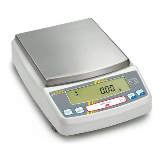
3 Appliance overview Models with readability d = 0.001 g: Models with readability d ≥ 0.01 g: Windshield Weighing pan Display Keyboard Levelling screw PBJ_N-SH-e-1810.docx... -
Page 7: Keyboard Overview
3.1 Keyboard overview In weighing mode: Pressed once and released Keep pressed for about 3 Button Description seconds Switches between the Exit menu / Return to weighing ON/OFF [ON/OFF] operation and standby modes. mode Invokes adjustment or menu To display the menu [CAL] MENU selection. -
Page 8: In Menu
3.2 In menu: Pressed once and released Keep pressed for about 3 Button Description seconds To return to a submenu or ON/OFF [ON/OFF] Return to weighing mode weighing mode. To display the menu [CAL] Moves to the next menu item. MENU element recently set. -
Page 9: Setting The Decimal Point When Entering Numerical Values
3.4 Setting the decimal point when entering numerical values Entering a decimal point is necessary only for determining the specific gravity or if a multiplier shall be defined for the user-defined unit. PRINT PRINT Repeat actuating the button until the last digit flashes. Actuate the button again in order to call up the decimal point setting mode. -
Page 10: Overview Of Display
3.5 Overview of display Display of units Capacity display Display Designation Description Indicates that the weighed value is stable. (*1) It marks the Stability display currently selected element during menu element selection. Tare symbol Informs about setting an initial tare value. It is displayed during adjusting the measuring range. -
Page 11: Basic Information (General)
The structure of the balance may not be modified. This may lead to incorrect weighing results, safety-related faults and destruction of the balance. The balance may only be used according to the described conditions. Other areas of use must be released by KERN in writing. 4.3 Warranty Warranty claims shall be voided in case... -
Page 12: Monitoring Of Test Resources
The responsible user must define a suitable interval as well as type and scope of this test. Information is available on KERN’s home page (www.kern-sohn.com with regard to the monitoring of balance test substances and the test weights required for this. -
Page 13: Unpacking, Setup And Commissioning
7 Unpacking, Setup and Commissioning Installation Site, Location of Use The balances are designed in a way that reliable weighing results are achieved in common conditions of use. You will work accurately and fast, if you select the right location for your balance. Therefore, observe the following for the installation site: Operate the device only indoors. - Page 14 Scope of delivery / serial accessories: Models with readability d ≥ 0.01 g: Models with readability d = 0.001 g: Wiindshield Weighing pan Carrier weighing pan Protective cover Main weighing unit 2 Fixiing screws 2 screws Protection hood Mains adapter Operating instructions Menu overview PBJ_N-SH-e-1810.docx...
-
Page 15: Placing
7.3 Placing Remove transport guard (models PBJ) To loosen the transport guard, turn both transport screws [1] anti-clockwise until they are locked (refer to sign [2]). For transport, turn both transport screws clockwise until they are locked. Mount safety hood Remove protective foil from adhesive strips and mount the safety hood so that it does not contact the weighing plate. - Page 16 While continuing to exert a slight pressure to the front side of the scale, turn out the rear foot screw until the scale stands in stable position. Check levelling regularly. Installation of weighing plate Models with readability d ≥ 0.01 g: PBJ_N-SH-e-1810.docx...
- Page 17 Models with readability = 0.001 g: Remove rubber plug as shown in picture. Attach wind guard and fix it by means of screws. Install weighing pan as per illustration. Note the correct position. Place the wind guard cover. PBJ_N-SH-e-1810.docx...
-
Page 18: Mains Connection
Power is supplied via the external mains adapter. The stated voltage value must be the same as the local voltage. Only use original KERN mains adapters. Using other makes requires consent by KERN. Models PBJ: Prior to mains connection, loosen the transport guard screws at the scale according to the sign in any case, see chapter 7.3... -
Page 19: Connection Of Peripheral Devices
Before connecting or disconnecting of additional devices (printer, PC) to the data interface, always disconnect the balance from the power supply. With your balance, only use accessories and peripheral devices by KERN, as they are ideally tuned to your balance. -
Page 20: Adjustment
8 Adjustment As the acceleration value due to gravity is not the same at every location on earth, each balance must be coordinated - in compliance with the underlying physical weighing principle - to the existing acceleration due to gravity at its place of location (only if the balance has not already been adjusted to the location in the factory). -
Page 21: Adjustment Test
TARE / Press the button and adjustment will take place automatically. After successful adjustment the balance automatically returns to weighing mode. In case of an adjustment error (e.g. objects on the weighing plate) the display will show an error message, repeat adjustment. ... -
Page 22: Adjustment Test With External Weight
9.1 Adjustment test with external weight Condition: Menu setting „E-tESt“ / Menu element 4 At verified balances, the adjustment test is locked by a switch (except accuracy class I). To disable the access lock, destroy the seal and actuate the adjustment switch. Fehler! Verweisquelle konnte nicht gefunden werden.Position of the adjustment switch see chap. -
Page 23: Adjustment Test With Internal Weight
press , the d-value is not reset to zero. No adjustment occurs. 9.2 Adjustment test with internal weight Condition: Menu setting „I-tESt“/ menu element 2 In weighing mode press . I-tESt is displayed. If „i-tESt“ is not displayed, press to return into weighing mode and activate menu element 2, see menu overview. -
Page 24: Automatic Adjustment By Psc (Perfect Self Calibration), Only Models Pbj
9.3 Automatic adjustment by PSC (Perfect Self Calibration), only models PBJ The PSC function determines the ambient temperature of the scale at any time. If the tolerance groups are exceed upwards or downwards, this is signalled and the necessary adjustment is carried out fully automatically. This will ensure that the scale is ready at any time. - Page 25 9.4 Automatic adjustment by Clock-CAL With the help of its internal adjusting weight and integrated clock the balance can be set to carry out automatic adjustment at set times (up to three times daily, „ACALt1“, „ACALt2“ und „ACALt3“). Clock-CAL is a very convenient function, when calibration logs are desired to be made for regular calibrations, or when wishing span calibrations during break times to avoid interruption of measurement work.
-
Page 26: Verification
10 Verification General introduction: According to EU directive 90/384/EEC or 2009/23EG balances must be officially verified if they are used as follows (legally controlled area): For commercial transactions if the price of goods is determined by weighing. For the production of medicines in pharmacies as well as for analyses in the medical and pharmaceutical laboratory. -
Page 27: The Menu
11 The menu 11.1 Navigation in the menu The menu consists of 7 groups and 4 levels. The configuration of the menu shows this structure where access to the required functions is facilitated by the numbering of the relevant menu elements. For navigation in the menu please use the enclosed menu is displayed. - Page 28 Menu group Flashing symbol Description Adjustment Analog display Capacity display, control and target weighing Installation environment and taring Application measurements and automatic output Conversion of units and specific weight measurement Setting of time and generation of an adjustment data Communication with external devices Making settings: As an example, the condition for evaluating the stability of 1 count (menu element 27) to 4 counts (menu element 29) shall be set.
- Page 29 , „Eb-1“ (menu element 27 ) is displayed. Press The stability display ( ) lights if „Eb-1“ is the current setting. , until „Eb-4“ (menu element 29 ) is displayed. Repeatedly press . „SET“ followed by the current setting „Eb-4“ is displayed, characterized by Save by the stability display ( ).
-
Page 30: Service, Maintenance, Disposal
Spilled weighing goods must be removed immediately. 12.2 Service, maintenance The appliance may only be opened by trained service technicians who are authorized by KERN. Before opening, disconnect from power supply. 12.3 Disposal Disposal of packaging and appliance must be carried out by operator according to valid national or regional law of the location where the appliance is used. -
Page 31: Instant Help
13 Instant help In case of an error in the program process, briefly turn off the balance and disconnect from power supply. The weighing process must then be restarted from the beginning. General display: Display Explication Wait for the next display. Date and time are output. -
Page 32: Error Message
13.1 Error message: Displayed error Explication Remedy code Disturbances in weight loading Check transport screws. mechanical elements. Weight on the scale pan is unstable during calibration. Large zero point drift during Empty the scale pan. calibration. Large drift during the PCAL function. Use the correct weight. - Page 33 Fault finding Procedures: Symptom Possible cause Remedy Mains adapter is not connected. Display is empty. Check mains voltage and The room mains circuit-breaker is connect the mains adapter switched off. correctly. Incorrect voltage. „OL” or „-OL” display The transport screws are not locked.
-
Page 34: Operating Method For The Adjustment Service
14 Operating method for the adjustment service 14.1 Gaining entry to the service menu Set balance to mass display mode. Verified balance Break the seal on base (bottom side). Set the slide switch on the back of the display board to ON. Connect the AC adapter. After a short time the display appears “OFF”. -
Page 35: Service Menu Contents
14.2 Service menu contents Version Number: indicates the model code. Absolute load value Load analog digital converter value Temperature analog digital converter value Power analog digital converter value Service CAL (writing in the simple linear coefficient) Loading an unloading the build-in calibration weight Initializing the build-in calibration weight value EEPROM (non-volatile memory) editor Calculating and wirting of the linear coefficient... -
Page 36: Balance Assembly / Dismantling Precautions
15 Balance assembly / dismantling precautions 15.1 Dismantling / Assembly Pull the connector out straight when disconnecting it. The connector must not be bent when pulling it out. Note:Failure to do so will bend the pins at the end and it will not be possible to re-insert the connector. -
Page 37: Dismantling
15.3 DISMANTLING Disconnect the AC adaptor and remove the Pan assembly (6) and the 4 Pan support caps (5).(Fig.2). Turn the balance upside down. Note: Place a cushioning material underneath the balance to prevent damage to the case when turning the balance upside down. (UW series only) If the balance is locked by two P4 M4X25 transportation screws (B11), unlock them in accordance with the explanation label. -
Page 38: Assembly
16 ASSEMBLY Fix the Assy,Pan support (4) loosely to the Unit assy (1) the two M4x10 hexagonal socket-head bolts (26) and Washer conical spring M4 (27) Set the pins of the Pan support positioning jig (J2) into the holes at the 4 corners of the Assy,Base (3). -
Page 39: Replacement Of Components
16.1 Replacement of Components 16.1.1 Replacing the Assy,Display (B4) Detach the Assy,Case (3) / Assy,Pan support (4) in accordance with the steps outlined in “3. Inspection of the Balance Interior”. Undo the CS-5 clip (15) which secures the Cable,45 (B7) and the Weight loader assy (10) cable, and pull out the connectors of the Weight loader assy (10) and Cable,45 (B7) at the Assy,Display (B4). - Page 40 Fig.7 Fig.8 PBJ_N-SH-e-1810.docx...
-
Page 41: Replacing The Assy,I/F (B5)
16.4 Replacing the Assy,I/F (B5) Detach the Assy,Case (3) / Assy,Pan support (4) in accordance with the steps outlined in “3. Inspection of the Balance Interior”. Undo the CS-5 clip (B15) securing Cable,flat26 (B6). Disconnect the Cable,flat26 (B6) connector from the Assy,I/F (B5). Unscrew the two P4 M4x8 screws (B10) fixing the Assy,I/F (B5). -
Page 42: Replacing The Assy,Detector (U8)
16.6 Replacing the Assy,Detector (U8) Detach the Assy,Case (3) / Assy,Pan support (4) in accordance with the steps outlined in “3. Inspection of the Balance Interior”. Disconnect the Cable,65 (U27) connector at the Assy,Analog (B3). Remove the two P3 M3x10 hexagonal socket-head bolts (U22) that fixes the Assy,Detector (U8) (Fig.11). -
Page 43: Replacing The Unit Assy (1)
16.8 Replacing the Unit assy (1) Detach the Assy,Case (3) / Assy,Pan support (4) in accordance with the steps outlined in “3. Inspection of the Balance Interior”. Disconnect the Cable,65 (U27) connector at the Assy,Analog (B3). Disconnect the Assy,Relay (U9) connector from the Assy,Analog (B3). Loosen the P3 M4X14 hexagonal socket-head bolt (25) fixing the Unit assy (1) in place to detach the Unit assy (1) (Fig.13). -
Page 44: Replacing The Force Coil Assy (L1)
17 Replacing the Force coil assy (L1) 17.1 Dismantling Detach the Unit assy (1) in accordance with the procedures outlined in steps 1) to 5) of “4.7 Replacing the Unit assy(1)”. Remove the soldering of the two PT-NI bands (U14) on the Assy,Lever (U4). Note: Do not break or damage the PT-NI band. - Page 45 Fix the new Force coil assy (L1) loosely to the Assy,Lever (U4) using the M2.5x6 screw (U25) and washer PB SPG M2.6 (U26), and solder the Twisted wire (U7) onto the Force coil assy (L1). Note: Left hand side of Force coil assy (L1): Yellow wire; Right hand side of Force coil assy (L1): Blue wire (Fig.17) Insert the Assy,Lever (U4) from the top of the unit and fix it loosely using the two M4X55 hexagonal socket-head bolts (20).
-
Page 46: Dismantling/ Assembling The Weight Loader Assy (10)
Fig.20 Fig.21 Pull the Lever fixing pin (J1) out of the lever fixing hole of the Unit assy (1). And shake the Unit assy (1) gently. Assembly is complete if the Assy,Lever (U4) goes up and down and hits the Lever stopper,(U12) making a clear sound in the process. Note: If a clear sound is not heard, either the Assy,Lever (U4) pin and the Stopper plate(U11), or the Force coil assy (L1) and the Assy,Magnet (U6), may be touching. - Page 47 Fig.22 Fig.23 PBJ_N-SH-e-1810.docx...
-
Page 48: Assembly
19.2 Assembly Replace the faulty component with a new one and screw fix it into place. Hook the Hooking shaft (W6) onto the Lever calibration weight support (W1), pass the Shaft (U12) through and insert the Snap ring D2 (W9). Fix the Assy,Push-up stick (W28) loosely to the Lever calibration weight support (W1) using the Nut (W14). -
Page 49: Balance Adjustment
20 Balance Adjustment 20.1 Adjustment of the Assy,Detector (U8) Height Detach the Assy,Case (3) / Assy,Pan support (4) in accordance with “3. Inspection of the Balance Interior”. Disconnect the Assy,Relay (U9) connector from Assy,Analog (B3) and adjust the height of the Assy,Detector (U8). Connect the (+) terminal of the voltmeter to the TP1 pin of the Assy,Analog (B3) and the (-) terminal to the TPG pin. -
Page 50: Adjustment Of Tilt Errors
20.2 Adjustment of tilt errors Detach the Assy,Case (3) in accordance with “3. Inspection of the Balance Interior”. Adjust the level of the balance using the 3 Level adjusters (B2) while referring to the level indicator, and then connect the AC adaptor to the balance. Insert the Pan support cap (5) into the Assy,Pan support (4), and place the Pan assembly (6) on top. -
Page 51: Adjustment Of Corner Load
20.3 Adjustment of Corner Load Warning: Perform corner load adjustment only when corner load error is within the below- listed amount. When corner load error is larger than this amount, replace Unit Assy (1). Adjustable corner load error limit : models with small pan, ±15mg, models with small pan, ±30mg, models with large pan, ±150mg, models with large pan, ±300mg Dismount ASSY, CASE (3) following “3. -
Page 52: Performance Inspection
21 Performance Inspection Performance inspections are to be conducted after at least 2 hours have passed since turning on the power and “g” display (back-light turn on ), in a location where there is no air movement, vibrations, or sudden temperature changes. Fit the supplied windbreak set onto models capable of minimum readings of 0.001g. -
Page 53: Linearity
If the error is large, perform PCAL (calibration of the built-in weight). For information, refer to the section on calibration of the built-in weight in the instruction manual. 21.4 Linearity Select menu “ E-CAL “ and calibration the span using the calibration weight. Load the weight as shown in “... -
Page 54: Component Replacement Precautions
22 Component Replacement Precautions The balance performance may change if the following components are replaced. Therefore, check the performance of the balance after replacement and make adjustments if necessary. Replacing Replacing Replacing Replacing Replacing Replacing Adjustment Items to be prepared Service act Unit assy Force coil... -
Page 55: Drawing
23 Drawing Fig.31 PBJ_N-SH-e-1810.docx... - Page 56 PBJ_N-SH-e-1810.docx...
- Page 57 Fig.33 PBJ_N-SH-e-1810.docx...
- Page 58 Fig.34 PBJ_N-SH-e-1810.docx...
-
Page 59: 11. Trouble Shooting
24 11. Trouble shooting 11.1 General trouble shooting Symptom Probable cause Remedy Correct power is not supplied. Check the power supply and connect correctly. Wrong AC adapter or failure Replace the AC adapter. (a) Nothing appears in the display. Cable, Flat26 (B6) is disconnected. Connect Cable,Flat (B6) correctly. - Page 60 Span calibration Perform span calibration. been (g)Sensitivity is performed correctly. Warm up is insufficient. Warm up sufficiently. correct. Level adjustment has not been done. Adjust level correctly. installation site Warm up sufficiently and perform span been calibration. changed. (UW only) Dust or dirt is stuck to Clean Weight(9).
-
Page 61: Information For Inferring The Cause Of Board Failure
24.1 Information for Inferring the Cause of Board Failure (All of these balances use only a few boards and the varied functions work in tandem with each other. It is therefore difficult to determine the failed board from a single breakdown mode. -
Page 62: Voltages Of Each Part (Reference Values)
24.4 Voltages of each part (reference values) 1. J25 connector; reference electrode ((4), (6): 0V) (pin number in brackets ( ) ) (3)-(4): 2 to 3V ((4); -pole) (1)-(2): 0.9 to 1.3V ((2); -pole) (5)-(6): 0V ((6); -pole) (7)-(6): 0V ((6);... -
Page 63: Writing In Simple Linear Coefficients (Temporary, Rough Adjustment Of Linearity)
24.7 Writing in Simple Linear Coefficients (temporary, rough adjustment of linearity) This procedure readies the balance for measurement for the time being after devices have been reassembled etc. Display “SvC_CAL” in the Service menu. . The balance will enter a “B” state that allows the setting of Press provisional linear constants (Ld30000 will flash). -
Page 64: Adjustment Of Linearity
25 Adjustment of Linearity Go into Service menu and set the balance so that wAd and tAd are usable. After the balance has been turned on for a sufficient amount of time at a stable room temperature, repeat the loading/ unloading of the following weights. The count data values are obtained by converting the absolute value of the weight used into the number of digits required. - Page 65 Record the data of the temperature data tAd (E.g: 00031627). (The Ad value is recorded as 8 digits. If the value does not amount to 8 digits, fill in the higher digits with “0”.) Record in turn the wAd values of weights 1 to 6 corresponding to each weighing capacity (If the value does not amount to 8 digits, fill in the higher digits with “0”).
-
Page 66: Editing Eeprom Data
26 Editing EEPROM data 26.1 Using “Edit” Edit is displayed through the Service menu mode (by repeatedly turning the ), and the Edit mode is selected with the key (the contents of the EEPROM will be displayed); at the same time, the storage register 10 will flash. Repeatedly turn the to select 4 (flashes) : registers numbered in the 40s are selected. - Page 67 to go to the single digit : The “0” of “40” will flash. Press the Press the to select 1 (flashes) : Register 41 is selected. Press the to provisionally set the data in register 41 : the contents of register 41 are displayed (the contents of the EEPROM will not be altered at this point).
Need help?
Do you have a question about the PBJ-N and is the answer not in the manual?
Questions and answers