Sign In
Upload
Download
Table of Contents
Contents
Add to my manuals
Delete from my manuals
Share
URL of this page:
HTML Link:
Bookmark this page
Add
Manual will be automatically added to "My Manuals"
Print this page
×
Bookmark added
×
Added to my manuals
Manuals
Brands
KERN Manuals
Scales
PBJ Series
Operating instructions manual
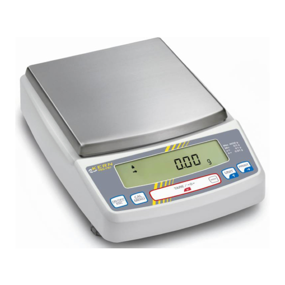
KERN PBJ Series Operating Instructions Manual
Precision balances
Hide thumbs
Also See for PBJ Series
:
Operating instructions manual
(75 pages)
1
Table Of Contents
2
3
4
5
6
7
8
9
10
11
12
13
14
15
16
17
18
19
20
21
22
23
24
25
26
27
28
29
30
31
32
33
34
35
36
37
38
39
40
41
42
43
44
45
46
47
48
49
50
51
52
53
54
55
56
57
58
59
60
61
62
63
64
65
66
67
68
69
70
71
72
73
74
75
76
77
78
page
of
78
Go
/
78
Contents
Table of Contents
Bookmarks
Table of Contents
Table of Contents
Technical Data
Declaration of Conformity
Appliance Overview
Keyboard Overview
Numeric Entry
Setting the Decimal Point When Entering Numerical Values
Overview of Display
Basic Information (General)
Proper Use
Improper Use
Warranty
Monitoring of Test Resources
Basic Safety Precautions
Pay Attention to the Instructions in the Operation Manual
Personnel Training
Transport and Storage
Testing Upon Acceptance
Packaging
Unpacking, Setup and Commissioning
Installation Site, Location of Use
Unpacking / Scope of Delivery
Placing
Mains Connection
Switch Power Supply on
Connection of Peripheral Devices
Initial Commissioning
Adjustment
Manual Adjustment by CAL Button
Adjustment with Internal Weight (Only Models PBJ)
Adjustment with External Weight (Factory Setting Models PBS)
Adjustment Test
Adjustment Test with External Weight
Adjustment Test with Internal Weight
Automatic Adjustment by PSC (Perfect Self Calibration), Only Models PBJ
Automatic Adjustment by Clock-CAL (Model PB Only)
ISO/GLP Log
Setting of Adjustment Protocol and Scale Identification Number
Verification
Basic Operation
Switch on off Balance
Zeroing
Simple Weighing
Taring
Underfloor Weighing
The Menu
Navigation in the Menu
Useful Functions
Recall of Last Menu
Resetting the Menu
Menu Lock
Set the Installed Clock
Date
Time
Setting the Display for the Standby Mode
Functions for Adaptation to Ambient Conditions
Stability and Reaction (Average Value)
Automatic Mode
Filling Mode
Standard Mode
Antivibration Mode
Antiwind Mode
Stability Detection Band
Tracking
Capacity Display
Switch-Over Weighing Unit
Percentage Conversion
Application Functions
Parts Counting
Control Weighing and Target Weighing
Control Weighing (Comparator) Display Type 1
Control Weighing (Comparator) - Display Type 2
Target Weighing Mode
Density Determination
Specific Measurement of Solid Weight
Table of Temperatures and Densities
Specific Measurement of Liquid Weight
Extreme Value Recording
Auto Print Function
Automatic Zero Setting
Zero Range
Taring /Printing at Stability (Models PBJ)
Formulation Mode
Automatic Saving and Zeroing
Animal Weighing
Data Output
Personal Computer - RS-232C
Connecting the Cable
Data Formats
For Measuring Values
For „Ol" or „-Ol
Using Codes of Commands
User Settings
Overview
Handshaking
Format
Speed of Communication
Parity / Bit Length
Stop Bits
Limiter
Service, Maintenance, Disposal
Clean
Service, Maintenance
Disposal
Instant Help
Advertisement
Quick Links
Download this manual
Operating instructions
Precision balances
KERN PBS/PBJ
Version 1.5
10/2015
GB
KERN & Sohn GmbH
Ziegelei 1
D-72336 Balingen
E-Mail: info@kern-sohn.com
Phone: +49-[0]7433- 9933-0
Fax: +49-[0]7433-9933-149
Internet: www.kern-sohn.com
PBS/PBJ-BA-e-1515
Table of
Contents
Previous
Page
Next
Page
1
2
3
4
5
Advertisement
Table of Contents
Need help?
Do you have a question about the PBJ Series and is the answer not in the manual?
Ask a question
Questions and answers
Related Manuals for KERN PBJ Series
Scales KERN PBJ 620-3NM Operating Instructions Manual
Precision balances (75 pages)
Scales KERN PBJ 420-3M Operating Instructions Manual
Precision balances (79 pages)
Scales KERN PBS 620-3M Operating Instructions Manual
Precision balances (79 pages)
Scales KERN PBS 4200-2M Operating Instructions Manual
Precision balances (79 pages)
Scales KERN PBS 6200-2M Operating Instructions Manual
Precision balances (79 pages)
Scales KERN PBS 8200-1M Operating Instructions Manual
Precision balances (79 pages)
Scales KERN PBJ-N Service Manual
Precision balances (67 pages)
Scales KERN PBS Series Operating Instructions Manual
Precision balances (78 pages)
Scales KERN PBJ 4200-2NM Operating Instructions Manual
Precision balances (75 pages)
Scales KERN PBJ 6200-2NM Operating Instructions Manual
Precision balances (75 pages)
Scales KERN ALJ Operating Manual
Analytical and precision balances (101 pages)
Scales KERN PCB Operating Manual
Precision balance (37 pages)
Scales KERN PLJ Series Operating Manual
Analytical and precision balances (84 pages)
Scales KERN ALS Series Operating Manual
Analytical and precision balances (86 pages)
Scales KERN PFB 120-3 Operating Manual
Pfb series precision balance (48 pages)
Scales KERN PCD Series Operating Instructions Manual
Precision balance (46 pages)
This manual is also suitable for:
Pbs series
Pbj-ba-e-1515
Pbs-ba-e-1515
Table of Contents
Print
Rename the bookmark
Delete bookmark?
Delete from my manuals?
Login
Sign In
OR
Sign in with Facebook
Sign in with Google
Upload manual
Upload from disk
Upload from URL


Need help?
Do you have a question about the PBJ Series and is the answer not in the manual?
Questions and answers