
Related Manuals for Eaton Cutler-Hammer ATVSKDA30300XSU


Summary of Contents for Eaton Cutler-Hammer ATVSKDA30300XSU
- Page 1 Cutler-Hammer I.B. ATS-V003 Instructions for Cutler-Hammer Transfer Switch Equipment (30 - 1000 Amperes) Effective June 1998 Supersedes ATS-VOO1 dated July 1997...
- Page 3 I.B. ATS-V003 Page iii TRANSFER SWITCH EQUIPMENT COVERED BY WARNING THIS INSTRUCTION BOOK IS DESIGNED AND TEST- ED TO OPERATE WITHIN ITS NAMEPLATE RAT- INGS. OPERATION OUTSIDE OF THESE RATINGS MAY CAUSE THE EQUIPMENT TO FAIL RESULTING READ AND UNDERSTAND THE INSTRUCTIONS IN DEATH, SERIOUS BODILY INJURY AND/OR CONTAINED HEREINAFTER BEFORE ATTEMPTING PROPERTY DAMAGE.
-
Page 4: Table Of Contents
I.B. ATS-V003 Page iv TABLE OF CONTENTS Page SECTION 1: INTRODUCTION Preliminary Comments and Safety Precautions....................1 1.1.1 Warranty and Liability Information ......................1 1.1.2 Safety Precautions ..........................1 General Information.............................1 1.2.1 Transfer Switch Types..........................2 1.2.2 Design Configuration ..........................2 Transfer Switch Catalog Number Identification ....................3 SECTION 2: RECEIVING, HANDLING AND STORAGE Receiving................................6 Handling ................................6... - Page 5 I.B. ATS-V003 Page v Page SECTION 6: TESTING AND PROBLEM SOLVING Testing ................................26 Problem Solving ..............................26 6.2.1 Transfer Switch Appears Inoperative ....................26 SECTION 7: MAINTENANCE Introduction................................28 Procedures ................................28 Effective 6/98...
- Page 6 I.B. ATS-V003 Page vi LIST OF FIGURES Figure Title Page Typical Automatic Transfer Switch Equipment Nameplate ...............iii Typical Load Transfer Switch (circuit breaker type) Schematic..............2 Vertical Design Automatic Transfer Switch Equipment with Deadfront Cover in Place Over Power Panel (225-1000 Amperes)..................3 Vertical Design Automatic Transfer Switch Equipment Shown with Deadfront Cover Removed (225-1000 Amperes) ..................3 Horizontal Design Automatic Transfer Switch Equipment (30-150 Amperes) ...........5...
-
Page 7: Section 1: Introduction
I.B. ATS-V003 Page 1 SECTION 1: INTRODUCTION NEL WITH THE STYLE OF PRESENTATION. THIS WILL HELP TO INSURE THAT PERSONNEL ARE ALERT TO WARNINGS, WHICH APPEAR THROUGH- 1.1 PRELIMINARY COMMENTS AND SAFETY OUT THE DOCUMENT. IN ADDITION, CAUTIONS PRECAUTIONS ARE ALL UPPER CASE AND BOLDFACE. This technical document is intended to cover most aspects associated with the installation, application, operation and maintenance of transfer switch equipment... -
Page 8: Transfer Switch Types
I.B. ATS-V003 Page 2 Non-Automatic Transfer Switch (Manually Operated) 1.2.1 TRANSFER SWITCH TYPES Non-Automatic transfer switches provide the main con- Four types of basic transfer switch equipment are avail- tacts and the transfer mechanism to effect the transfer able: of the main contacts from source to source. Transfer of power, however, is accomplished by true hand opera- Automatic Transfer Switch tion (not power assisted) of the transfer switch. -
Page 9: Transfer Switch Catalog Number Identification
I.B. ATS-V003 Page 3 Example: Catalog Number (circled numbers corre- For the vertical design, installed power panel positioning bolts, elongated mounting holes and pre-tapped inserts spond to position headings in Table 1.1) – insure proper power panel mounting after initial enclo- sure installation or when switching from top to bottom entry and vice versa. - Page 10 I.B. ATS-V003 Page 4 Table 1.1 Transfer Switch Catalog Number Explanation Positions 1-2 Position 3 Position 4 Positions 5-6 Basic Switching Device Control Switching Device Orientation Panel Device Automatic Transfer Switch Vertical IQ Transfer Cutler-Hammer Series C Horizontal Microprocessor Cutler-Hammer Series C Non-Automatic Transfer Switch NT Solid State Logic Cutler-Hammer Series C...
-
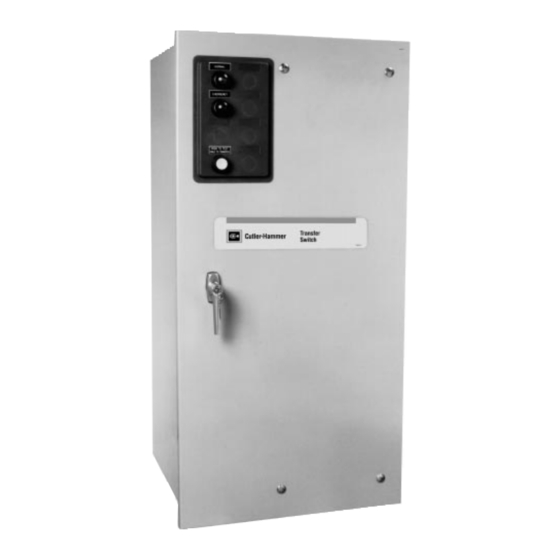
Page 11: Horizontal Design Automatic Transfer Switch Equipment (30-150 Amperes)
I.B. ATS-V003 Page 5 Figure 1-4 Horizontal Design Automatic Transfer Switch Equipment (30-150 Amperes) Effective 6/98... -
Page 12: Section 2: Receiving, Handling And Storage
I.B. ATS-V003 Page 6 SECTION 2: RECEIVING, HANDLING AND ner posts. An egg crate design cardboard protector cov- ers the entire top of the enclosure with additional card- STORAGE board protectors over the indicating light panel and operating handle. A heavy duty cardboard lid covers the 2.1 RECEIVING entire opening. -
Page 13: Section 3: Equipment Description
I.B. ATS-V003 Page 7 SECTION 3: EQUIPMENT DESCRIPTION The enclosed automatic transfer switch consists of three basic panels interconnected through connector plugs and mounted in an enclosure (Figures 1-3, 1-4, 4-4 and 3.1 GENERAL 4-5): Cutler-Hammer transfer switch equipment is available in •... -
Page 14: Vertical Design Steel Base Plate
I.B. ATS-V003 Page 8 3.2.1 VERTICAL DESIGN STEEL BASE PLATE A solid steel shield attached to the ratchet assembly permits viewing of the rotary switch position indicator The steel base plate on the vertical design permits the while restricting access to other parts of the power panel power panel to be moved vertically within the enclosure (Figure 1-2). -
Page 15: Voltage Selection Panel
I.B. ATS-V003 Page 9 3.3 VOLTAGE SELECTION PANEL 3.5 OPTIONS (NON-LOGIC PANEL) The voltage selection panel is a multi-tap enclosed Switch options, which are not part of the logic scheme, transformer mounted in the enclosure (Figure 3-4). are available to meet a variety of other application Seven front accessible voltages taps from 208 to 600 requirements. -
Page 16: Charger Mounting Dimensions In Inches (Mm)
I.B. ATS-V003 Page 10 NOTICE 6 1/8 Not all options are available for all transfer switch con- figurations. If in doubt, check Price List 29-920 for the availability of options for a specific transfer switch design. The option numbers used here correspond to the numbers used in the price list. -
Page 17: Enclosure
I.B. ATS-V003 Page 11 33. Shunt Trip The shunt trip is wired to terminal blocks for customer connection. (120V coil supplied as standard.) A. Supplied in Normal Breaker B. Supplied in Emergency Breaker 34. Extender Cable An extender cable provides a means for extending the distance between the power switching panel and the logic panel. -
Page 18: Standards
I.B. ATS-V003 Page 12 a. In emergency systems, in accordance with articles Table 3.1 Transfer Switch Equipment Enclosures 517 and 700 in the National Electrical Code, ANSI/NFPA 70 and the National Fire Protection NEMA Design Protection Association No. 76A and/or Type b. -
Page 19: Section 4: Installation And Wiring
I.B. ATS-V003 Page 13 SECTION 4: INSTALLATION AND WIRING Check to make certain that there are no pipes, wires or other mounting hazards in the immediate mounting area that could create a present or future problem. 4.1 GENERAL Carefully remove all packing material from the transfer Transfer switches are factory wired and tested. -
Page 20: Enclosed Automatic Transfer Switch Dimensions And Approximate Weights
I.B. ATS-V003 Page 14 Top of Lugs on Power Panel Gutter Space Power Transformer Panel Panel Logic Panel Plan View Note: Run power cables behind transformer panel in the gutter space provided. Front View Side View Approx. Switch Type Power Panel Enclosure Gutter Space Bolt Pattern... -
Page 21: Vertical Design Load Lug Location
I.B. ATS-V003 Page 15 See Figure “1” .88 (22) 4.5 (114) Location for Neutral Strap in Top Entry Position Location for Neutral Strap in Bottom Entry Position 4.5 (114) Location Holes for Top Entry .17R .88 (22) .69 (18) .25 (6) .38R Location Holes for Bottom Entry... -
Page 22: Vertical Design Load Lug Assembly Shown Mounted
I.B. ATS-V003 Page 16 load lugs are to be repositioned to the bottom, do it at Step 1: Disconnect the power panel from the rest of the this time before wiring the unit or making power cable transfer switch by unplugging the connector connections. -
Page 23: Typical (225-1000 Amperes) Vertical Design Transfer Switch Equipment (Door Open And Deadfront Shield Removed)
I.B. ATS-V003 Page 17 Load Lugs Normal Power Source Transformer Panel (Top Entry) Molded Case Switch Power Panel Neutral Door Mounted Connections Logic Panel Manual Operating Handle Motor Disconnect (S3) Indicator Wheel Voltage Selection Transfer Panel Mechanism Voltage Selection Connectors Engine Start Contacts (Red Terminals) -
Page 24: Typical (30-150 Amperes) Horizontal Design Transfer Switch Equipment (Door Open)
I.B. ATS-V003 Page 18 Emergency Normal Power Power Source Source Switching Switching Device Device Normal Line Emergency Line Connections Connections Transfer Mechanism Load Connections Neutral Voltage Selection Assembly Connectors Disconnect Connectors Voltage Engine Start Selection Panel Contacts (Red Terminals) Figure 4-5 Typical (30-150 Amperes) Horizontal Design Transfer Switch Equipment (Door Open) Step 8: Remount the operating mechanism to the front Step 10: With the power panel held securely against the of the power panel with the six bolts removed... -
Page 25: Power Cable Connections
I.B. ATS-V003 Page 19 4.5 POWER CABLE CONNECTIONS Step 5: Carefully strip insulation from the power cables. Avoid nicking or ringing of the conductor strands. Prepare the stripped conductor termi- WARNING nation end by cleaning it with a wire brush. If aluminum conductors are used, apply an appro- priate joint compound to the clean conductor POWER CONDUCTORS MAY HAVE VOLTAGE PRE-... -
Page 26: Wiring
I.B. ATS-V003 Page 20 CAUTION CAUTION DO NOT RUN POWER CABLES BEHIND OR TO THE CHECK THE TRANSFER SWITCH EQUIPMENT LEFT OF THE POWER PANEL. THE CABLES NAMEPLATE FOR RATED VOLTAGE. IT SHOULD SHOULD BE RUN IN THE GUTTER SPACE PROVID- BE THE SAME AS THE NORMAL AND EMERGENCY ED AS SHOWN IN FIGURE 4-1. - Page 27 I.B. ATS-V003 Page 21 CAUTION BE SURE THAT THE CORRECT VOLTAGE IS SELECTED TO MATCH THE SYSTEM VOLTAGE. AN IMPROPER SELECTION AND/OR CONNECTION COULD RESULT IN EQUIPMENT DAMAGE. Vertical Design Voltage Selection The vertical design transfer switch is furnished with a multi-tap Voltage Selection Panel to the right of the power panel.
-
Page 28: Section 5: Operation
I.B. ATS-V003 Page 22 SECTION 5: OPERATION 5.2 VERTICAL DESIGN OPERATION The vertical design transfer switch utilizes a mechanical 5.1 GENERAL mechanism with a manual operating handle (Figure 4- 4). The manual operating handle can be used to create A transfer switch provides main contacts to connect and the rotational motion required to open and close the disconnect the load to and from the normal and emer- main contacts through a rigid mechanical interlocking... -
Page 29: Horizontal Design Operation
I.B. ATS-V003 Page 23 equipped transfer switches, are mounted external to the NOTICE molded case switches and operated by the rotating lever. Each limit switch is synchronized with its associat- ed switch to operate when the switch closes. If a transfer switch with any kind of electrical operat- ing capabilities is to be operated manually utilizing When manually operating the transfer switch, the trans- the manual operating handle, it is strongly recom-... -
Page 30: Non-Automatic Operation (Manually Operated)
I.B. ATS-V003 Page 24 5.4 NON-AUTOMATIC OPERATION (MANUALLY Pushing and holding the pushbutton causes the motor OPERATED) to operate and automatically transfer the load by open- ing and closing the main contacts. Since an intelligence A non-automatic (manually operated) transfer switch circuit is not part of the design, operation of the pushbut- (Paragraph 1.2.1) functions as described in Paragraphs ton is required each time an electrical transfer is... - Page 31 I.B. ATS-V003 Page 25 Normal Source Restoration • A return to the normal power source begins when the voltage in all phases of a three phase sensing unit or line-to-line in a single phase sensing unit is restored to its operating range. •...
- Page 32 I.B. ATS-V003 Page 26 SECTION 6: TESTING AND PROBLEM WARNING SOLVING 6.1 TESTING ONLY PROPERLY TRAINED PERSONNEL FAMILIAR WITH THE TRANSFER SWITCH EQUIPMENT AND After transfer switch equipment is initially installed or dur- ITS ASSOCIATED EQUIPMENT SHOULD BE PERMIT- ing planned outages, the installation should be tested to TED TO PERFORM THE PROBLEM SOLVING FUNC- insure that all equipment operates properly.
- Page 33 I.B. ATS-V003 Page 27 Step 3: Verify that the voltage selection plug is in the proper position to match the system voltage. Step 4: Look for any obviously overheated components. Determine the cause and rectify, if possible. Replace defective components after the cause is determined.
- Page 34 I.B. ATS-V003 Page 28 SECTION 7: MAINTENANCE and the importance placed on dependable operation by this type of equipment, inspection and maintenance checks should be made on a regularly scheduled basis. 7.1 INTRODUCTION Since equipment maintenance will consist mainly of keeping the equipment clean, the frequency of mainte- nance will depend, to a large extent, on the cleanliness WARNING...
- Page 35 I.B. ATS-V003 Page 29 Table 7.1 Periodic Maintenance Procedures Step Action a. Make transfer switch equipment safe for Disconnect line power from equipment being serviced by inspection and/or maintenance. opening next highest disconnect device. Make certain that any accessory control power is switched off by disconnect- ing all logic plugs.
- Page 36 I.B. ATS-V003 Page 30 Effective 6/98...
- Page 37 I.B. ATS-V003 Page 31 Effective 6/98...
- Page 38 I.B. ATS-V003 Page 32 Effective 6/98...
- Page 40 I.B. ATS-V003 This instruction booklet is published solely for informa- tion purposes and should not be considered all inclu- sive. If further information is required, you should con- sult Cutler-Hammer. Sale of product shown in this literature is subject to terms and conditions outlined in appropriate Cutler- Hammer selling policies or other contractual agreement between the parties.
Need help?
Do you have a question about the Cutler-Hammer ATVSKDA30300XSU and is the answer not in the manual?
Questions and answers