Eaton ATC-300 O & M Manual
2-position contactor based transfer switch
Hide thumbs
Also See for ATC-300:
- Instruction booklet (52 pages) ,
- Operation and maintenance manual (42 pages) ,
- O & m manual (40 pages)
Table of Contents
Advertisement
Quick Links
O & M Manual for ATC-300 2-Position
Contactor Based Transfer Switch
Instruction Booklet
Description
Introduction . . . . . . . . . . . . . . . . . . . . . . . . . . . . . . . . . . 2
Receiving, Handling, and Storage . . . . . . . . . . . . . . . . . . . 6
Equipment Description . . . . . . . . . . . . . . . . . . . . . . . . . . . 7
Installation and Wiring . . . . . . . . . . . . . . . . . . . . . . . . . . .14
Operation . . . . . . . . . . . . . . . . . . . . . . . . . . . . . . . . . . . .20
Testing and Problem Solving . . . . . . . . . . . . . . . . . . . . . . .21
Adjustments . . . . . . . . . . . . . . . . . . . . . . . . . . . . . . . . . .23
Maintenance . . . . . . . . . . . . . . . . . . . . . . . . . . . . . . . . . .23
Renewal Parts Guide . . . . . . . . . . . . . . . . . . . . . . . . . . . .24
Appendix A: Pickup / Dropout Tables . . . . . . . . . . . . . . . . .35
IB01602015E
Page
For more information visit: www.eaton.com
Advertisement
Table of Contents

Subscribe to Our Youtube Channel
Related Manuals for Eaton ATC-300


Summary of Contents for Eaton ATC-300
-
Page 1: Table Of Contents
Renewal Parts Guide ......24 ATC-300 Contactor Based ATS Quick Start Instructions . . .25 Appendix A: Pickup / Dropout Tables . -
Page 2: Introduction
In no event will Eaton be responsible to the purchaser or user in contract, in tort (including negligence), strict liability or... - Page 3 1.2.1 Design Configuration Source 2 The Eaton contactor based ATS is a compact design that uses a power contactor to transfer essential loads from one power source to another (Figure 3 [100A]).
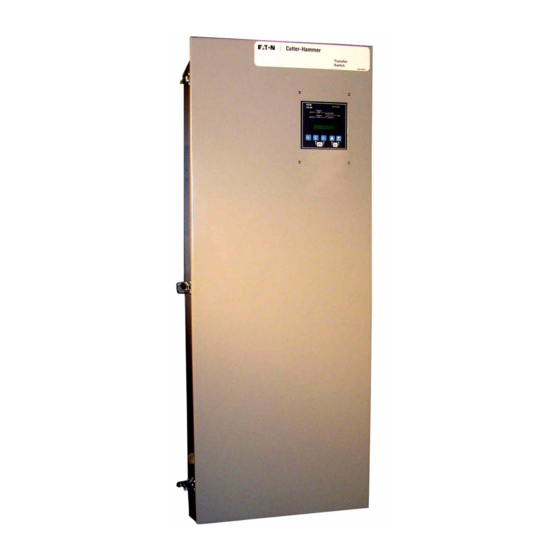
- Page 4 2 pole, 2 position Power Contactor mounted on a baseplate within the enclosure. The intelligence represented by the logic panel is ATC-300 controller. The continuous current rating of this equipment is 400A and applicable at 240 Vac, 60 Hz. The transfer switch equipment is enclosed in a NEMA 3R enclosure and is listed for UL applications.
- Page 5 Instruction Booklet ATC-300 2-Postion Contactor Effective: August 2010 Page 5 Based Transfer Switch Table 2. Transfer Switch Catalog Number Explanation POSITIONS 1 TO 2 POSITION 3 POSITION 4 POSITIONS 5 TO 6 BASIC DEVICE SWITCHING DEVICE CONTROL PANEL SWITCHING DEVICE...
-
Page 6: Receiving, Handling, And Storage
Record any external and internal damage for reporting to the transportation carrier and Eaton, once a thorough inspection is complete. All claims should be as specific as possi- ble and include the catalog and General Order numbers. -
Page 7: Equipment Description
Instruction Booklet ATC-300 2-Postion Contactor Effective: August 2010 Page 7 Based Transfer Switch Section 3: Equipment Description 3.1 General The ATS consists of three basic panels: 1. The power panel; 2. The voltage selection and transformer panel (if required); and 3. - Page 8 Effective: August 2010 Based Transfer Switch Figure 8. ATC-300 Logic Control Panel. The ATC-300 controller has an operating temperature of -20 to 70°C (-4 to 158°F). Figure 7. Standard Voltage Selection Terminals (Shown The controller circuit board is protected by an insulating confor- Connected to the 480 Vac Taps).
- Page 9 Adjustable Overfrequency: 3.5.1 Standard Features Dropout: 103 - 105% of nominal Pickup:101% to (Dropout -1Hz) of nominal The following is a list of the standard features for the ATC-300 Controlled ATS. 5D. 1-Phase Undervoltage Time Delay Normal to Emergency (TDNE) Adjustable Undervoltage:...
- Page 10 12G. Source 1 - Available Test Operators This feature provides a white LED that, when lit, indicates Eaton ATSs are provided with a Test Pushbutton that simu- Source 1 is available. lates a loss of the Source 1 power source as standard (Fea- ture 6B).
- Page 11 Instruction Booklet ATC-300 2-Postion Contactor Effective: August 2010 Page 11 Based Transfer Switch 23K. Plant Exerciser Selectable – Disabled/1/7/14/28 Day Inter- 26L. Source 1 3-Phase Voltage Unbalance .For a 3-phase wye source, this feature monitors phase This feature provides for automatic test operation of the voltage ratios.
- Page 12 18W. Ammeter A single ammeter is a true RMS sensing device that dis- The following is a list of the optional features for the ATC-300 Controlled ATS. All features or combinations of features may not plays single phase current only.
- Page 13 Dust, Dirt, and Non-Corrosive Liquids 3.7 Standards Eaton ATS equipment, enclosed in any of the enclosures listed in Table 3, is listed for application by UL and ULC. In addition, Eaton ATSs are listed in File E38116 by Underwriters Laborato- ries, Inc.
-
Page 14: Installation And Wiring
4.3 Mounting Procedure 4.1 General CAUTION Eaton ATSs are factory wired and tested. Installation requires SINCE THE ENCLOSED ATS MUST BE LIFTED INTO PLACE FOR solidly mounting the enclosed unit and connecting power cables MOUNTING, BE CERTAIN THAT ADEQUATE RESOURCES ARE and auxiliary pilot circuits. - Page 15 TO THE ATS EQUIPMENT BEFORE BEGINNING TO WORK WITH THE nectors at the back of the ATC-300 logic panel. CONDUCTORS AND/OR TERMINATING THEM TO THE EQUIPMENT. Remove the wire ties securing the harness to the inside of the door.
- Page 16 The engine control contact connections are located on the logic panel of the ATS. Connect the engine start wires to the terminals marked 13 and 14 on J-5 connector on the ATC-300 Controller (see Figure 12). A contact closes between these terminal when an engine start signal is provided by the ATS logic.
- Page 17 9 10 11 12 13 14 9 10 11 12 13 14 9 10 9 10 Output Relays Control Inputs 6.5 in. Figure 12. Location of Terminals 13 and 14 on the J-5 Connector of ATC-300 Controller. IB01602015E For more information visit: www.eaton.com...
- Page 18 WHEN CHANGING THE VOLTAGE, ONE WIRE MUST BE MOVED ON THE PRIMARY TAPS OF BOTH TRANSFORMERS. Figure 13B. Standard Voltage Selection Panel. Figure 13. Step 3: Reinstall the cover and tighten the four screws. For more information visit: www.eaton.com IB01602015E...
- Page 19 Instruction Booklet ATC-300 2-Postion Contactor Effective: August 2010 Page 19 Based Transfer Switch 4.8 Terminal Block Wire Installation and Removal Proceed with the following steps and associated figures to install or remove terminal block wiring. Step 1: Figure 14 shows two tension clamp terminal blocks.
-
Page 20: Operation
300 Controller Instruction Booklet IB01602009E) if values are above 130 Vac or below 110 Vac. 2. Disconnect the J7 connector from the ATC-300 controller. 11. Insert the J7 connector into the controller. 3. Locate the manual lever on the left side of the contactor. -
Page 21: Testing And Problem Solving
Instruction Booklet ATC-300 2-Postion Contactor Effective: August 2010 Page 21 Based Transfer Switch Section 6: Testing and Problem Solving 5.3 Automatic Transfer The operating sequence of an ATS is dictated by the switch's 6.1 Testing standard features and selected options. Operation of an ATS... - Page 22 EQUIPMENT AND ITS ASSOCIATED EQUIPMENT, SHOULD BE PER- MITTED TO PERFORM THE PROBLEM SOLVING FUNCTION. IF AN Note:The ATC-300 Logic Controller provides the capability to set the INDIVIDUAL IS NOT QUALIFIED TO PERFORM THE PROBLEM SOLV- Engine Test function to: ING FUNCTION, THE INDIVIDUAL SHOULD NOT ATTEMPT ANY OF THESE PROCEDURES.
-
Page 23: Adjustments
Carefully remove the arc chute clips using needle nose pliers. Remove the arc chutes to inspect the contacts. Contact Eaton Care (1-877-ETN-CARE, Option-2) if the contacts have excessive wear. Reinstall the arc chutes and arc chute clips, making sure the ends of the clips are fully seated in the grooves on the barriers. -
Page 24: Renewal Parts Guide
ATS renewal parts. For more information, please see Renewal Parts Publication (RP01603002E). ATC-300 Controller - 2 Position Contactor type (In-Phase) - CAT#8160A00G27 Power Panel (Cont.) 100A (Domestic Switch), 600VAC, 2-Pole - Cat# 68C8471G11 Transformer Pack 100A, 2-Pole, 3-Pole, 4-Pole - Cat# 68B2584G04... -
Page 25: Atc-300 Contactor Based Ats Quick Start Instructions
Quick Start Instructions WARNING THESE QUICK START INSTRUCTIONS ARE NOT A COMPLETE SOURCE OF INFORMATION ON THE ATC-300 CONTROLLED ATS EQUIPMENT. INSTALLATION SHOULD NOT BE STARTED UNTIL THE ENTIRE INSTRUCTION BOOK HAS BEEN REVIEWED AND UNDERSTOOD. FAILURE TO FOLLOW THE FULL INSTRUCTIONS CAN RESULT IN DEATH, SEVERE PERSONAL INJURY, OR PROP- ERTY DAMAGE. - Page 26 Page 26 Effective: August 2010 Based Transfer Switch NEUTRAL CONNECTIONS MANUAL OPERATING HANDLE NORMAL POWER SOURCE TRANSFER MECHANISM EMERGENCY POWER SOURCE LOAD LUGS POWER PANEL VOLTAGE SELECTION PANEL Figure 21. 100A, 3-Pole, ATS Interior Components. For more information visit: www.eaton.com IB01602015E...
- Page 27 Step 4: Connect the Engine Generator Start wires to terminals Genset manufacturer instruction leaflet for recom- 13 and 14 on the J-5 connector on the ATC-300 Con- mended wire sizes and location procedures. troller (Figure 22). This contact is CLOSED whenever...
- Page 28 Bypass Alarm Reset TDNE / TDEN Figure 23. ATC-300 Logic (Utility Supplying Load). Step 6: To view the setpoints, press the <Step/Enter> pushbut- ton and enter the Password. Note: The factory default Password is 0300. Once all installation and testing is complete, the Password should be changed by authorized personnel to a unique Password for the equipment.
- Page 29 Instruction Booklet ATC-300 2-Postion Contactor Effective: August 2010 Page 29 Based Transfer Switch Utility - Generator Transfer Switch Source 1 is available Close Source 1 (Energize K1) Source 1 is powering the load Source 1 becomes unavailable Is Source 1...
- Page 30 (Energize K1) Open Source 1 (Energize K2) Close Source 1 (Energize K1) Close Source 2 (Energize K2) Source 1 is powering the load Source 2 is powering the load Figure 25. Dual Utility Transfer Switch. For more information visit: www.eaton.com IB01602015E...
- Page 31 Instruction Booklet ATC-300 2-Postion Contactor Effective: August 2010 Page 31 Based Transfer Switch In-Phase Transition Implementation Source 1 is available Close Source 1 (Energize K1) Source 1 is powering the load Receive request to transfer to Source 2 (or Engine Test, Plant Exercise, Go To Emergency) TDES timer times out Send "Engine Start"...
- Page 32 0:20 TDEF Seconds Time Delay Emergency Fail Timer 0 sec to 6 sec IN-PHASE Hertz In-phase Transition 0 or 1 (1=Enabled) IP FREQ DIFF Hertz In-phase Transition Frequency Difference 0.0 Hz to 3.0 Hz For more information visit: www.eaton.com IB01602015E...
- Page 33 Instruction Booklet ATC-300 2-Postion Contactor Effective: August 2010 Page 33 Based Transfer Switch Table 6. Setpoint Possibilities (cont’) SETPOINT SETPOINT UNITS DESCRIPTION RANGE FACTORY DEFAULT SYNC TIME Minutes In-phase Transition Synchronization Timer 1 min to 60 min PHASE REV...
- Page 34 NOTICE tor checked for proper voltage and frequency output. Step 9: Initiate a Load Test from the front panel of the ATC-300 WHILE PERFORMING TESTING, IF AN UNDESIRED OR UNDOCU- (Figure 28). This may be done by setting the engine test MENTED RESULT OCCURS, FIRST CONTACT THE LOCAL GENSET DEALER.
-
Page 35: Appendix A: Pickup / Dropout Tables
Instruction Booklet ATC-300 Contactor Effective: August 2010 Page 35 Based Transfer Switch Appendix A: Pickup / Dropout Tables UNDERVOLTAGE PICKUP / DROPOUT TABLE PERCENTAGE VOLTAGE Pickup Dropout IB01602015E For more information visit: www.eaton.com... - Page 36 Page 36 Effective: August 2010 Based Transfer Switch OVERVOLTAGE PICKUP / DROPOUT TABLE PERCENTAGE VOLTAGE Dropout Pickup UNDERFREQUENCY PICKUP / DROPOUT TABLE PERCENTAGE FREQUENCY Pickup Dropout OVERFREQUENCY PICKUP / DROPOUT TABLE PERCENTAGE FREQUENCY Dropout Pickup For more information visit: www.eaton.com IB01602015E...
- Page 37 Instruction Booklet ATC-300 2-Postion Contactor Effective: August 2010 Page 37 Based Transfer Switch Notes: IB01602015E For more information visit: www.eaton.com...
- Page 38 Instruction Booklet ATC-300 2-Position Contactor Page 38 Effective: August 2010 Based Transfer Switch Notes: For more information visit: www.eaton.com IB01602015E...
- Page 39 Instruction Booklet ATC-300 2-Postion Contactor Effective: August 2010 Page 39 Based Transfer Switch Notes: IB01602015E For more information visit: www.eaton.com...
- Page 40 DEALING OR USAGE OF TRADE, ARE MADE REGARDING THE INFORMATION, RECOMMENDATIONS AND DESCRIPTIONS CONTAINED HEREIN. In no event will Eaton be responsible to the purchaser or user in contract, in tort (including negligence), strict liability or otherwise for any special, indirect, incidental or conse-...
Need help?
Do you have a question about the ATC-300 and is the answer not in the manual?
Questions and answers