
Related Manuals for Bitronics M350

Summary of Contents for Bitronics M350
- Page 1 M350 3-Phase Ammeters & Voltmeters User Manual September 27, 2017 ML0038 Document Revision M © 2017 by Bitronics, LLC...
- Page 2 - 2 - ML0038 September 27, 2017 Copyright 2017 Bitronics, LLC...
-
Page 3: Table Of Contents
3.1.1 Specifications (per section 1.3) ..................... 25 3.2 M350 V3 VT Inputs – VA, VB, VC, VN (See Appendix A1 and Section 1.3) ........25 3.3 M350 A3 CT Inputs – IA, IB, IC (See Appendix A1 and section 1.3) ..........25 ... - Page 4 5.2 HTML Web Server ..........................41 5.3 Passwords ............................. 41 5.4 Navigating the M350’s setup menu from the front panel ..............43 5.5 Performing set-up through the web page interface ................46 6.0 MEASUREMENTS ..........................60 ...
-
Page 5: Series Manual Set
2010-03-25 M650M3x51x models with firmware download capability V1.030 2010-05-14 Add 0-1mA, add per-phase power demands to protocols V1.040 2010-06-17 Add M350 models, add configurable display screens V1.050 2010-07-14 Add secondary volts screens, more info to front panel menu V1.060 2010-07-20 Add support for B3 models V1.070... -
Page 6: Certification
If the equipment is used in a manner not specified by Bitronics LLC, the protection provided by the equipment may be impaired. -
Page 7: Authorized Representative In The European Union
Copyright 2002-2008 Mark Adler inarp uses WinPcap, which is Copyright 1999-2005 NetGroup, Politecnico di Torino (Italy), and 2005-2010 CACE Technologies, Davis (California). TRADEMARKS The following are trademarks or registered trademarks of Bitronics, LLC: Bitronics logo Bitronics PowerPlex... -
Page 8: Safety Section
Terminals exposed during installation, commissioning and maintenance may present a hazardous voltage unless the equipment is electrically isolated. - 8 - ML0038 September 27, 2017 Copyright 2017 Bitronics, LLC... - Page 9 Do not attempt to perform installation, maintenance, service or removal of this device without taking the necessary safety precautions to avoid shock hazards. De-energize all live circuit connections before work begins. - 9 - ML0038 September 27, 2017 Copyright 2017 Bitronics, LLC...
-
Page 10: Warning: Emissions - Class A Device (En55011)
Any products containing batteries should have them removed before disposal, taking precautions to avoid short circuits. Particular regulations within the country of operation may apply to the disposal of lithium batteries. - 10 - ML0038 September 27, 2017 Copyright 2017 Bitronics, LLC... -
Page 11: Description & Specifications
1.0 DESCRIPTION & SPECIFICATIONS 1.1 Introduction The M350 family of 3-phase ammeters and voltmeters provides a range of measurement and communications capabilities for 3-phase metering. They offer an outstanding display, superior communications flexibility and easy setup. The following Model M350 meter types are covered in this manual:... - Page 12 Common Mode Reads to 400V peak, any input-to-case (ground) Input Voltage Impedance >12M ohms, input-to-case (ground) Voltage 2.5kV rms 1min, input-to-case (ground) Withstand 2kV rms 1min, input-to-input Frequency 45-65 Hz - 12 - ML0038 September 27, 2017 Copyright 2017 Bitronics, LLC...
- Page 13 Sampling System Sample Rate 64 samples per cycle Data Update Rate Amps, Volts Available every 100 ms Number of Bits - 13 - ML0038 September 27, 2017 Copyright 2017 Bitronics, LLC...
- Page 14 Single port; LC fiber 100 Base-FX (option) Analog Transducer Refer to section 7.0 for specifications Outputs (option*) *Either the serial port or analog output may be ordered as an option, but not both - 14 - ML0038 September 27, 2017 Copyright 2017 Bitronics, LLC...
- Page 15 Indoor use; Indoor/Outdoor use when mounted in an appropriately rated protective enclosure to NEMA or IP protection classifications, as required for the installation. Class 1 equipment to IEC61140: 2001 - 15 - ML0038 September 27, 2017 Copyright 2017 Bitronics, LLC...
- Page 16 RJ45, 8 position modular jack, Category 5 for copper connection; 100m (328 ft.) UTP (unshielded twisted pair) cable. Weight 1.8 lbs (.8 kg) (typical) Size Industry standard 4” round case, 7.0 inches long - 16 - ML0038 September 27, 2017 Copyright 2017 Bitronics, LLC...
-
Page 17: Environment
If applicable, the CE mark must be prominently marked on the case label. European Community Directive on EMC (EMCD) 2014/30/EU, superseding 2004/108/EC and Directive 91/263/EC [TTE/SES]. European Community Directive on Low Voltage (LVD) 2014/35/EU, superseding 2006/95/EC - 17 - ML0038 September 27, 2017 Copyright 2017 Bitronics, LLC... - Page 18 Immunity to Radiated Electromagnetic Energy (Radio Frequency) EN 61000-4-3: 2006 + A1: 2008 + A2:2010, Class III Frequency: 80 – 1000 MHz, Amplitude: 10.0 V/m, Modulation: 80% AM @ 1 kHz - 18 - ML0038 September 27, 2017 Copyright 2017 Bitronics, LLC...
- Page 19 AC Supply Voltage Dips and Short Interruptions EN 61000-4-11: 2004 Surge Withstand Capability Test For Protective Relays and Relay Systems ANSI/IEEE C37.90.1: 2002 (2.5kV oscillatory wave and 4kV EFT) - 19 - ML0038 September 27, 2017 Copyright 2017 Bitronics, LLC...
-
Page 20: Physical Construction & Mounting
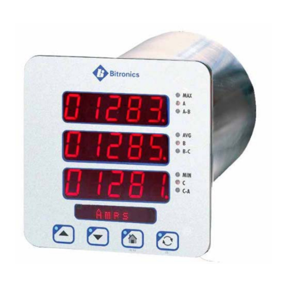
2.0 PHYSICAL CONSTRUCTION & MOUNTING The M350 meters are packaged in rugged aluminum case specifically designed to meet the harsh conditions found in utility and industrial applications. The Front panel view of the V3 3-phase voltmeter is shown in Figure 1. The A3 3- phase ammeter is not shown, but would look similar indicating Amps for engineering units. - Page 21 Figure 2 - Mounting and Overall Dimensions M350 - 21 - ML0038 September 27, 2017 Copyright 2017 Bitronics, LLC...
-
Page 22: Initial Inspection
Bitronics instruments are carefully checked and "burned in" at the factory before shipment. Damage can occur however, so please check the instrument for shipping damage as it is unpacked. Notify Bitronics LLC immediately if any damage has occurred, and save any damaged shipping containers. -
Page 23: Cleaning
Cleaning the exterior of the instrument shall be limited to the wiping of the instrument using a soft damp cloth applicator with cleaning agents that are not alcohol based, and are non-flammable and non-explosive. - 23 - ML0038 September 27, 2017 Copyright 2017 Bitronics, LLC... -
Page 24: Back Panel & Wiring
3.0 BACK PANEL & WIRING The rear view of the M350 is shown in figure 3 with the option port shown (removable terminal block at the top), which may be selected at order time, as either, the serial communication option, the 0-1mA analog transducer output option, or the 4-20mA analog transducer output option. -
Page 25: Auxiliary Power
Operating Range: 36-300V dc, 55-275V ac (45-65Hz) 3.2 M350 V3 VT Inputs – VA, VB, VC, VN (See Appendix A1 and Section 1.3) The M350 V3 meter voltage (VT) signal inputs are connected to terminals 3-6 (see Appendix A1 for specific wiring configurations). Voltage signals are measured using a 12M ohm resistor divider with a continuous voltage rating of 7kV. -
Page 26: Serial Ports (See Section 4.2)
Transformers (CTs). 3.4 Serial Ports (See section 4.2) The M350 meters are equipped with an optional serial port. The port is software (user) configurable for RS-232 or RS-485. The RS-232 drivers support full and half duplex modes. See Figures 7-8 for signal assignments. - Page 27 Enter Network addresses using the meter’s front buttons: Refer to the section in this manual on “Navigating the M350’s setup menu from the Front panel” for further instruction regarding the button sequence you will use to scroll through the menu structure.
- Page 28 Although the IP address can be obtained via the display, for versions that don’t have a display (M651, M661, PPX II), Bitronics has created a utility program to request the IP address for a specific MAC address on an Ethernet network. This program can be used with the M650 as well.
-
Page 29: Indicators - Ethernet (Act) & Serial Leds
The ability to upgrade Firmware is done over the Ethernet port. The M350 family utilizes a page in the Web Server interface to upload and install new firmware. A password protected hyperlink is provided from the Configuration Settings Page that navigates to the Firmware Upload page. - Page 30 Figure 4 – Bitronics M350 Firmware Upload Page Once the Firmware Upload page is visible, use the Browse button to locate the firmware image on your computer. Next use the Submit button to initiate the file transfer and installation process. The instrument must be rebooted to make the new firmware active.
-
Page 31: Operation
4.0 OPERATION 4.1 Display The M350 meters can display several per-phase quantities for the circuit being monitored. In order to make all quantities available, the display scrolls from quantity to quantity approximately every 5 seconds. The quantities are refreshed once a second. - Page 32 Phase A-B Maximum Average Volts 00000 Phase B-C Maximum Average Volts 00000 Phase C-A Maximum Average Volts X Volts (LED to right of the top line will light up the MAX legend) - 32 - ML0038 September 27, 2017 Copyright 2017 Bitronics, LLC...
- Page 33 10. 00000 Phase A-B Secondary Volts 00000 Phase B-C Secondary Volts 00000 Phase C-A Secondary Volts SecVolts - WYE meters only - DELTA meters only X - indicates blank, (k)ilo - 33 - ML0038 September 27, 2017 Copyright 2017 Bitronics, LLC...
- Page 34 (ENABLED/DISABLED) by the user. This programming can be done through the web server. (Refer to section 5.5) From the web page, select the Settings tab then click on Screen Enable in the menu list. - 34 - ML0038 September 27, 2017 Copyright 2017 Bitronics, LLC...
-
Page 35: Overview - Buttons Functions
4.1.1 Overview – Buttons Functions Figure 5 – Button functions for Display Mode Figure 6 – Button functions in Set-up Mode - 35 - ML0038 September 27, 2017 Copyright 2017 Bitronics, LLC... -
Page 36: Keypad Functions For Display Mode
Auto scroll state (ON/OFF) is stored in non-volatile memory. Pressing the Home (Enter) key will bring up the home screen. The factory default home screen will be Amps A, B, C for M350 A3. If a user enables or disables screens via the front display buttons from Setup Mode - Scrn Ena, then the home screen will automatically become the 1 enabled screen. -
Page 37: Display Error Messages
This may configuration. Error cause communication errors. Firmware FLASH Will be displayed during download and Reboot meter Download in will disappear shortly after user reboots when prompted. Progress meter - 37 - ML0038 September 27, 2017 Copyright 2017 Bitronics, LLC... -
Page 38: Serial Port
(3 1/3 characters) from the time the transmitter shuts off to the next message on the bus in order to guarantee reliable communications. See figure 7 below for RS485 cable wiring diagrams. - 38 - ML0038 September 27, 2017 Copyright 2017 Bitronics, LLC... - Page 39 Figure 7 - Typical RS-485 Cable Wiring - 39 - ML0038 September 27, 2017 Copyright 2017 Bitronics, LLC...
- Page 40 Figure 8 – RS-232 Cable Wiring Diagram - 40 - ML0038 September 27, 2017 Copyright 2017 Bitronics, LLC...
-
Page 41: Functional Description
5.0 FUNCTIONAL DESCRIPTION 5.1 Configuration Setup of the M350 meters is most easily performed using the web interface via the Ethernet service port. Basic configuration can also be handled from the front display by entering the setup mode. 5.2 HTML Web Server The M350 incorporates an internet-compatible HTML web page. - Page 42 A user has five attempts to enter the correct password. If unsuccessful, the unit will be locked out for 5 minutes before another attempt can be made. - 42 - ML0038 September 27, 2017 Copyright 2017 Bitronics, LLC...
-
Page 43: Navigating The M350'S Setup Menu From The Front Panel
5.4 Navigating the M350’s setup menu from the front panel - 43 - ML0038 September 27, 2017 Copyright 2017 Bitronics, LLC... - Page 44 - 44 - ML0038 September 27, 2017 Copyright 2017 Bitronics, LLC...
- Page 45 Highlight Previous/Next digit. Exit to menu EXIT How to Enter a Floating Point Number: Increment highlighted digit by 1. ENTER Shifts decimal point one place to right. Decimal moves to left‐most digit when right‐most digit is passed. Highlight Next digit. Highlights left‐most digit when right‐ most digit is passed. Exit to menu EXIT How to Enter an IP address: Increment highlighted digit by 1. ENTER Highlight Previous/Next digit. Numbers scroll left and right to follow highlighted digit. Exit to Network menu EXIT - 45 - ML0038 September 27, 2017 Copyright 2017 Bitronics, LLC...
-
Page 46: Performing Set-Up Through The Web
(Navigating the M350’s setup menu from the Front panel) to change your network configuration settings. Enter the M350’s IP address into your internet browser to connect with the M350 web page interface. Internet browsers supported are Firefox, Internet Explorer, Safari and Google Chrome. - Page 47 Data page (M350 V3): Two Views, Instantaneous and Demands - 47 - ML0038 September 27, 2017 Copyright 2017 Bitronics, LLC...
- Page 48 Data page (M350 A3): Two Views, Instantaneous and Demands Resets page (M350 A3):From this page select the quantity to be reset and click apply - 48 - ML0038 September 27, 2017 Copyright 2017 Bitronics, LLC...
- Page 49 Settings page: Click on one of the settings categories (Identity, Input, Network, Serial Port, Protocol, Screen Enable, Load/Store Settings, Password Security, or Firmware Upload) to be taken to the next page. Contact Page: - 49 - ML0038 September 27, 2017 Copyright 2017 Bitronics, LLC...
- Page 50 Protocol – This page allows user configuration of the protocols – DNP or Modbus Screen Enable - Allows the screens shown on the M350 display (front panel) to be enabled or disabled by the user. The webpage must be used in order to enable screens on the M350.
- Page 51 Identity: Input (M350 A3 Shown): - 51 - ML0038 September 27, 2017 Copyright 2017 Bitronics, LLC...
- Page 52 Network: - 52 - ML0038 September 27, 2017 Copyright 2017 Bitronics, LLC...
- Page 53 DNP3 can be found in the Appendix of the respective protocol manuals. There are both fixed and configurable register/point lists. Please refer to the appropriate protocol manual for more information regarding how to view or edit the register/point list. - 53 - ML0038 September 27, 2017 Copyright 2017 Bitronics, LLC...
- Page 54 Modbus DNP3 - 54 - ML0038 September 27, 2017 Copyright 2017 Bitronics, LLC...
- Page 55 DNP Serial DNP TCP - 55 - ML0038 September 27, 2017 Copyright 2017 Bitronics, LLC...
- Page 56 Modbus RTU Modbus TCP - 56 - ML0038 September 27, 2017 Copyright 2017 Bitronics, LLC...
- Page 57 Screen Enable (M350 V3 Shown): Analog Output (if option ordered; M350 V3 Shown): - 57 - ML0038 September 27, 2017 Copyright 2017 Bitronics, LLC...
- Page 58 Load/Store Device Settings: Password Security Settings: - 58 - ML0038 September 27, 2017 Copyright 2017 Bitronics, LLC...
- Page 59 Firmware Upload: - 59 - ML0038 September 27, 2017 Copyright 2017 Bitronics, LLC...
-
Page 60: Measurements
1:1 CT or 1:1 VT depending upon the model. These values can be entered into the M350 over the network or via front display buttons or web page, and will be stored in internal non-volatile memory. All measurements are presented in primary units, based on these ratios. -
Page 61: Demand Measurements
M350 V3 must create it from the vector sum of the other two phase-to-neutral voltages. In order to configure the M350 V3 for 2½ element mode and which phase voltage is missing, select one of the following: 2.5 element - A, 2.5 element - B, or 2.5 element –... -
Page 62: Ampere Demand (M350 A3)
6.4.4 Demand Interval The M350 uses 900 seconds (15 minutes) as the default demand interval for current in the A3. The default for average volts and average power measurements is 60 seconds in the V3. -
Page 63: Heartbeat And Health Check
The table below provides a reference of error codes. The Health Check value shown in the M350 web live data page is a hexadecimal representation of the binary value. For example, a Health Check value of 0000 0014 is the equivalent of the binary value 000000000010100. -
Page 64: Calibration
6.8 Instantaneous Measurement Principles The M350 measures all signals at an effective rate of 64 samples/cycle, accommodating fundamental signal frequencies from 45 to 65Hz depending on model. Samples of all bus signals are taken using a 16-Bit A/D converter, effectively creating 64 "snapshots"... -
Page 65: Analog (Transducer) Output Option
The connections for the 0-1mA output option are shown in figure 9, while the connections for the 4-20 mA with external and internal loop are shown in figure 10. - 65 - ML0038 September 27, 2017 Copyright 2017 Bitronics, LLC... - Page 66 Figure 9 – 0-1mA Transducer Output Connections (A3 Shown) - 66 - ML0038 September 27, 2017 Copyright 2017 Bitronics, LLC...
- Page 67 Figure 10 – 4-20mA Transducer Output Connections (A3 Shown) - 67 - ML0038 September 27, 2017 Copyright 2017 Bitronics, LLC...
-
Page 68: Appendix
APPENDIX A1 CT/VT Connection Diagrams Figure 11 – Voltage Signal Connections – M350 V3 - 68 - ML0038 September 27, 2017 Copyright 2017 Bitronics, LLC... - Page 69 Figure 11 – Voltage Signal Connections – M350 V3 - 69 - ML0038 September 27, 2017 Copyright 2017 Bitronics, LLC...
- Page 70 Figure 12 – Current Signal Connections – M350 A3 - 70 - ML0038 September 27, 2017 Copyright 2017 Bitronics, LLC...
-
Page 71: A2 Ethernet Troubleshooting
Some hubs/switches will not output an optical idle unless they receive an optical idle. This then inhibits the converter from outputting a copper link pulse enabling the M350 to link. In this condition, no device completes the link. - Page 72 - 72 - ML0038 September 27, 2017 Copyright 2017 Bitronics, LLC...
-
Page 73: A3 M350 Display Screens - Visual Representations
A3 M350 Display Screens – Visual Representations M350 A3 - 73 - ML0038 September 27, 2017 Copyright 2017 Bitronics, LLC... - Page 74 M350 V3 - 74 - ML0038 September 27, 2017 Copyright 2017 Bitronics, LLC...
- Page 75 - 75 - ML0038 September 27, 2017 Copyright 2017 Bitronics, LLC...
- Page 76 - 76 - ML0038 September 27, 2017 Copyright 2017 Bitronics, LLC...
- Page 77 - 77 - ML0038 September 27, 2017 Copyright 2017 Bitronics, LLC...
- Page 78 - 78 - ML0038 September 27, 2017 Copyright 2017 Bitronics, LLC...
- Page 79 - 79 - ML0038 September 27, 2017 Copyright 2017 Bitronics, LLC...
- Page 80 E. DeMicco added new DoC document 5/22/17 Updated standards information in E. DeMicco section 1.5 R. Fisher 9/27/17 Corrected information on allowable E. DeMicco password character, fixed dimension drawing - 80 - ML0038 September 27, 2017 Copyright 2017 Bitronics, LLC...
- Page 81 - 81 - ML0038 September 27, 2017 Copyright 2017 Bitronics, LLC...
- Page 82 Bitronics, LLC 261 Brodhead Road, Bethlehem, PA. 18017 (610) 997-5100 Fax (610) 997-5450 www.novatechweb.com /bitronics...
Need help?
Do you have a question about the M350 and is the answer not in the manual?
Questions and answers