Advertisement
Quick Links
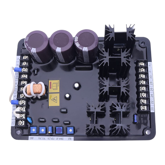
INTRODUCTION
The AVC63-12 and AVC125-10 regulate the
level of excitation supplied to the field of a
conventional, brushless, synchronous gen-
erator.
Regulation is achieved by sensing the gen-
erator output voltage, converting it to a dc
signal, and comparing the signal to a refer-
ence voltage. An error signal is developed
and used to control the dc field power in
order to maintain a constant generator out-
put.
Each regulator includes frequency compen-
sation with selectable slope, inverse-time
overexcitation shutdown, buildup circuitry,
single- or three-phase voltage sensing, sin-
gle- or three-phase shunt or permanent
magnet generator (PMG) power input, paral-
lel droop compensation, and an accessory
input. The accessory input provides com-
patibility with devices such as var/power
factor controllers or excitation limiters.
SPECIFICATIONS
Power Input ∗
Configuration:
1-phase or 3-phase
Frequency:
50 to 400 Hz
Voltage Range
AVC63-12:
90 TO 153 Vac
AVC125-10:
180 to 264 Vac
Maximum Continuous Burden
AVC63-12:
1,092 VA
AVC125-10:
1,750 VA
∗ See Options for Inrush Current Reduction
Module information.
Sensing Input
Configuration:
1-phase or 3-phase
Burden:
<1 VA per phase
Voltage Range
Option A:
90 to 139 Vac
Option B:
180 to 264 Vac
Nominal Frequency
Option 1:
50 or 60 Hz
Option 2:
400 Hz
(See Table 4 for style/option information.)
Accessory Input
Voltage Range: ±3 Vdc
Power Output
Maximum Continuous Output
AVC63-12:
12 Adc at 63 Vdc
AVC125-10:
10 Adc at 125 Vdc
10 Second Forcing Output
AVC63-12:
24 Adc at 125 Vdc
AVC125-10:
20 Adc at 250 Vdc
Minimum Field Resistance
5.25 Ω
AVC63-12:
12.5 Ω
AVC125-10:
Regulation Accuracy
±0.5% of voltage setpoint, average response
Voltage Drift
±0.5% variation for a 40°C (104°F) change
Response Time
<4 ms
Publication
9337200991
AUTOMATIC VOLTAGE REGULATOR
AVC63-12 AND AVC125-10
Frequency Compensation
One or two jumper-selectable V/Hz curves
with knee frequency adjustable from 45 to
65 Hz (50/60 Hz units) or 300 to 430 Hz
(400 Hz units). Refer to Figure 1 (60 Hz) and
Figure 2 (400 Hz) for sensing models.
EMI Suppression
Internal filter. (See CE Conformity )
Voltage Buildup
Automatic voltage buildup occurs from re-
sidual generator voltage as low as 6 Vac
(AVC63-12) or 12 Vac (AVC125-10).
Overexcitation Shutdown
Overexcitation shutdown protection reduces
the output voltage to zero in the times
shown below for the listed voltages. Other
voltages and times are based on the inverse
time characteristic curves of Figures 3 and 4
AVC63-12
125 Vdc, ±10% in approximately 10 s
210 Vdc, ±10% in approximately 1 s or less
AVC125-10
250 Vdc, ±10% in approximately 10 s
370 Vdc, ±10% in approximately 1 s or less
Droop/Line Drop Compensation
<10 VA adjustable from 0 to 10% of rated
input current at 0.8 power factor. (LDC com-
pensates only for voltage drop due to line
reactance and reactive components of the
load current.)
Agency Approvals
UL Recognition
Standard 508, File E97035
CSA Certification
Standard CAN/CSA-C22.2 No. 14-95,
File LR 23131
CE Conformity
Radiated Emissions
EN50081-2
Conducted Emissions
EN50081-2 (EN55011, Class A)
Conducted Emissions
EN50081-2 (EN55011, Class A)
ESD Immunity
EN50082-2 (4 kV contact, 8 kV air)
EFT Immunity
EN50082-2 (2 kV coupling clamp)
Magnetic Immunity
EN50082-2 (30 Arms, 50 Hz)
Safety
EN61010-1
Radiated Immunity
Electric Field: EN61000-4-3 (10 V/m)
Conducted:
Type Tests
Shock
Withstands 20 G in each of 3 mutually per-
pendicular planes.
Vibration
Withstands 4.5 G at18 to 2,000 Hz
Physical
Temperature
Operating:
Revision
D
FOR
EN61000-4-6 (10 Vrms)
–40 to 70°C (–40 to 158°F)
Storage:
–40 to 70°C (–40 to 158°F)
Max. Humidity: 95%, non-condensing
Weight:
approx. 1.1 kg (2.5 lb)
INSTALLATION
Regulators are contained in an encapsu-
lated plastic case and may be mounted in
any convenient position. A regulator may be
mounted directly on a genset using UNF ¼-
20 or equivalent hardware. Hardware selec-
tion should be based on any expected ship-
ping/transportation and operating conditions.
The torque applied to the mounting hard-
ware should not exceed 65 in-lb (7.34 N•m).
See Figure 5 for regulator dimensions.
CONNECTIONS
Before connecting the voltage regulator into
your system, review the terminal descrip-
tions listed in Table 1 and the connection
diagrams in Figures 6 through 8.
Table 1. Terminal Descriptions
Term #
Description
CH GND Chassis ground connection
2
Auxiliary input from SCP250
and/or EL 200 (See Fig. 7)
3
4
Internal voltage adjust: con-
nect to 7. External voltage
adjust: no connection
5
1 A current transformer (CT)
5a
5 A CT
6
CT common connection
6a
Common connection for
selectable features
7
Internal voltage adjust: con-
nect to 4. External voltage
adjust: connect to 6a
8
Connect to 6a to select 1
V/Hz underfrequency slope
9
Connect to 6a to select
3-phase sensing
20
C-phase sensing input
22
A-phase sensing input
24
B-phase sensing input
26
1- or 3-phase power input
28
3-phase power input
30
1- or 3-phase power input
F1
Field + connection
F2
Field – connection
ADJUSTMENTS
AVC63-12 and AVC125-10 adjustments are
described in the following paragraphs.
Field Flashing
When the regulator is operated with the
generator for the first time, the residual
magnetism may not be of sufficient magni-
tude or the correct polarity. If the generator
residual voltage is less than 6 Vac for the
AVC63-12 or 12 Vac for the AVC125-10 at
terminals 26, 28 and/or 30, shut down the
prime mover and proceed with the following
steps.
First Printing: 06/01
Copyright
Revised: 03/06
2006
Advertisement

Related Manuals for Basler AVC63-12A1


Summary of Contents for Basler AVC63-12A1
- Page 1 AUTOMATIC VOLTAGE REGULATOR AVC63-12 AND AVC125-10 Storage: –40 to 70°C (–40 to 158°F) INTRODUCTION Frequency Compensation One or two jumper-selectable V/Hz curves Max. Humidity: 95%, non-condensing The AVC63-12 and AVC125-10 regulate the with knee frequency adjustable from 45 to level of excitation supplied to the field of a Weight: approx.
- Page 2 The Basler EL 200 provides an initial, fast- tion just begins. be helpful in the troubleshooting process. acting limit of the field current at a user-...
- Page 3 Power Model components such as remote adjust potenti- Observe that the lamp turns on. AVC63-12A1 50/60 ometers and other non-essential items can Adjust the VLT ADJ control until the be helpful in the troubleshooting process.
- Page 4 Part of AVC63-12 Part of EL200 P0009-25 AVC125-10 08-15-05 AVC units may be connected to either the EL 200 or the SCP 250 using the terminals as shown in place of this series Part of interconnection. See the unit instruction SCP250 manuals for more information.