Table of Contents
Advertisement
HITEC Sensor
Developments
OPERATORS MANUAL
Process Monitor And Control Instrument
PMAC 3000
This manual covers version 2.03‐2.05(‐E) of the PMAC 3000.
This manual covers version 2.03 of the GUI software.
October 5, 2017
HITEC Sensor Developments
1050 W. Silver Bell Road
Orion, MI 48359
(248) 391‐3000
Fax: (248) 391‐0107
sales@hitecsensors.com
www.hitecsensors.com
Advertisement
Table of Contents

Related Manuals for HITEC PMAC 3000


Summary of Contents for HITEC PMAC 3000
- Page 1 HITEC Sensor Developments OPERATORS MANUAL Process Monitor And Control Instrument PMAC 3000 This manual covers version 2.03‐2.05(‐E) of the PMAC 3000. This manual covers version 2.03 of the GUI software. October 5, 2017 HITEC Sensor Developments 1050 W. Silver Bell Road Orion, MI 48359 (248) 391‐3000 Fax: (248) 391‐0107 sales@hitecsensors.com www.hitecsensors.com...
-
Page 2: Table Of Contents
Table of Contents Introduction ....................... 1 System Overview ........................ 1 Features .......................... 1 Power Up ...................... 2 Process Monitor Functions ................. 4 Track ............................ 4 The Track Display ........................ 5 +Peak, ‐Peak & +/‐ Peak ...................... 5 The Peak Display ......................... 7 Record ............................ 8 The Manual Record Display ... -
Page 3: Introduction
Six process monitoring functions, including: A continuous tracking function 3 peak logging functions 2 waveform recording functions (with multiple record rates) 4 process control output signals (for High, Ok, Low and Target occurrences) Programmable set‐points for Threshold, Target, High and Low Limits Analog Output Storage capacity in excess of 750,000 peak readings Storage capacity in excess of 3,000,000 record readings Storage capacity of up to 30 recordings Automatic calibration with HITEC Sensor Developments autoID sensors Measures with respect to absolute or relative zero Multiple engineering unit capability with automatic unit conversion Menu Locking Automatic power down timer Rechargeable Lithium‐Ion battery Support for third party sensors User selectable display colors User selectable display brightness Optional quadrature encoder support ... -
Page 4: Power Up
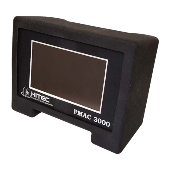
DIGITAL I/O PMAC 3000 SENSOR S/N: XXXXXX Figure 1 – PMAC 3000 Front, Top, and Rear View The first screen to appear describes the unit as a PMAC 3000 made by HITEC Sensor Developments. The software number is also displayed. See Figure 2. Figure 2 – Start‐up Screen P M A C 3 0 0 0 ... - Page 5 If a sensor is connected to the sensor input connection on the rear of the PMAC 3000 (see Figure 1), the next screen will be the Sensor Capacity screen. See Figure 3. This screen describes the capacity of the sensor in engineering units, as well as if there is an optional encoder installed. If the sensor is a HITEC Sensor Developments autoID sensor, the sensor information will reflect the autoID data. If the sensor does not have the autoID feature installed, the sensor information is that of the last sensor connected. Figure 3 – Sensor Capacity Screen After a short time, the PMAC 3000 will show the active Process Monitor Function. See Figure 4. Figure 4 – Typical Process Monitor Screen Figure 4 is just an example of the Process Monitor Functions. The actual screen to be displayed will reflect the Process Monitor Function that was active the last time the PMAC 3000 powered down. P M A C 3 0 0 0 Page 3 ...
-
Page 6: Process Monitor Functions
Left to itself, depending on the power down timer setting, the PMAC 3000 will power down on its own with no activity. The user may force a power down by pressing and holding the ON button until the display says “Release button to power down.” This takes about 2 seconds. If, for any reason, the PMAC 3000 has locked up, the device may be reset in this manner as well. In this case, however, it may not display “Release button to power down.” Just hold the button a few seconds and release it. Process Monitor Functions The PMAC 3000 provides six process monitoring functions: Track +Peak ‐Peak +/‐Peak Auto Record Manual Record Track Track provides continuous monitoring of a process. The instrument takes readings at 10,000 readings/second and averages them to display 4 readings/second. Track is designed for slowly changing processes. See Figure 5 for the typical Track display. ... -
Page 7: The Track Display
The Track Display Function: Track – Defines the current function. In this case, the Track function. Z‐Rel – Defines the Zero mode. Sensor Zero can be reference to an absolute zero or a relative zero, indicated respectively by Z‐Abs and Z‐Rel. Nov 11, 2013 & 4:11:34 PM ‐ These values represent the current date and time. They are updated in real time. Battery Indicator – A visual indication of how much charge remains in the battery. 0.0000 – Represents the current live load on the sensor. This value is updated in real time. lb – Represents the selected engineering units for the sensor. High, Pass and Low – Limit indicators, showing in real time, the status of the load on the sensor. Menu – Clicking Menu enters the PMAC 3000 Menu. See the Menu section. + Peak – Represents the other 5 functions. Clicking this button will change the Function mode to whichever function is displayed in the button. The function displayed in the button, and therefore activated by the button, is selected in the PMAC 3000 Menu. See the Menu section. Tare – Clicking Tare will zero the sensor. In Z‐Abs mode, the zero will be taken from the absolute zero reference inside the PMAC 3000. In Z‐Rel mode, the zero will be the current load on the sensor. Note: Each of the limit indicators has a corresponding output available on the Digital I/O connector. See Figure 1. In addition, there is a 4 output not reflected on the display that triggers ... - Page 8 +/‐Peak captures the largest peak magnitude, regardless of the sign of the load. It may be either positive or negative. The user defined sensor Threshold, and all limits, are evaluated with respect to the absolute value of the reading, so that the sign of the reading does not play a part in the evaluation, beyond the setting of the peak mode (ie. +Peak, ‐Peak or +/‐Peak). Figure 6 Figure 7 Figure 8 shows the typical peak display. P M A C 3 0 0 0 Page 6 ...
-
Page 9: The Peak Display
Figure 8 – Peak Screen The Peak Display Function: +/‐Peak – Defines the current function. In this case, the +/‐Peak function. Other options are +Peak and –Peak. Z‐Rel: #1 – Defines the Zero mode. Sensor Zero can be reference to an absolute zero or a relative zero, indicated respectively by Z‐Abs and Z‐Rel. See Track mode for how to zero the sensor. In addition, the #1 represents the count of the last acquired peak. In the case shown here, this is the 1st peak in memory. Oct 22, 2013 & 12:06:55 PM – These values represent the date and time of the last acquired peak. Battery Indicator – A visual indication of how much charge remains in the battery. 21.0475 – Represents the last peak load to be captured. N – Represents the selected engineering units for the sensor when the last peak was captured. High, Pass and Low – Limit indicators, showing the status of the last peak captured. Menu – Clicking Menu enters the PMAC 3000 Menu. See the Menu section. Track – Clicking Track will switch to the Track mode. As stated earlier, Track is the special case function that does not require a trip through the menu to activate. Redo Peak – Pressing Redo Peak will erase the last captured peak from memory. The display will then show the previous peak in memory. The PMAC 3000 may hold in excess of 750,000 peak readings. Memory is shared with the Record functions, so if any recordings are stored in memory, it will reduce the peak storage capacity. In ... -
Page 10: Record
to see a positive value in inlb. The display is unchanged from before because the display is showing the last peak captured. The next peak to be captured will reflect the changes that the user has made. Record The Record functions sample the sensor at a rate of 10,000 readings/second. The sample rate is user selectable down to 1 reading/second. In the case of any sample rate lower than 10,000 readings/second, the PMAC 3000 will still sample at the 10,000 readings/second and will average the readings to produce the user selected sample rate. In Auto Record, the process starts when a reading is greater than or equal to the user defined sensor Threshold value and ends when the reading stays below 80% of the user defined sensor Threshold value for more than 100 milliseconds. Upon the expiration of the 100 millisecond timer, the process is considered complete and the display will show an indication that recording ... -
Page 11: The Manual Record Display
Figure 9 – Manual Record Screen The Manual Record Display Function: M‐Rec (1kHz) – Defines the current function. In this case, the Manual Record function. The other option is A‐Rec (Automatic Record). In addition, the (1kHz) represents the currently selected sample rate. The sample rate is user adjustable in the menu from 10kHz down to 1Hz in pre‐defined increments. See the Menu section. Z‐Rel: #1 – Defines the Zero mode. Sensor Zero can be reference to an absolute zero or a relative zero, indicated respectively by Z‐Abs and Z‐Rel. See Track mode for how to zero the sensor. In addition, the #1 represents the count of the last recorded plot. In the case shown here, the last recorded plot was the 1st plot in memory. Battery Indicator – A visual indication of how much charge remains in the battery. Ready to Record – Informs the user that the PMAC 3000 is ready to begin recording. Menu – Clicking Menu enters the PMAC 3000 Menu. See the Menu section. Track – Clicking Track will switch to the Track mode. As stated earlier, Track is the special case function that does not require a trip through the menu to activate. Start Rec – Pressing Start Rec will begin the recording process. While recording is in progress, this line will change to Recording… See Figure 10. Figure 10 – Recording Active Screen P M A C 3 0 0 0 Page 9 ... - Page 12 Note (in Figure 10) the change to Z‐Rel: #2, indicating the current recording is plot #2. Also, note that the time and date of the current recording are shown, and that the Start Rec button now shows Stop Rec. Pressing Stop Rec will end the recording process. It is also possible to start and stop manual recording by using the external cycle‐on input. Activating the cycle‐on input will cause recording to begin. Deactivating cycle‐on will cause recording to stop. See the section on external digital I/O connections for more information. When recording ends, the Recording Complete screen will appear. See Figure 11. ...
-
Page 13: Encoder (Optional)
Encoder (optional) The PMAC 3000 is available with an encoder option. This option is easily verified at power up when the software version is displayed in the Startup Screen. See Figure 2. At the end of the software version, “‐E” will appear. The encoder version works with quadrature encoders with single ended TTL/CMOS outputs. It powers the encoder with 5VDC. There are three modes of operation that relate to the encoder. These modes are Off, Angle and RPM. How to select the appropriate mode is discussed in the Menu section later in this manual. In the Off mode, the PMAC 3000 behaves just like it would with the standard software (no encoder software). In the Angle mode, all encoder measurements are made in degrees. In the RPM mode, all encoder measurements are made in RPM. In the case of Angle and RPM modes, the display is split such that the sensor reading is on the left and the encoder reading on the right. The appropriate units are shown below the corresponding reading. The encoder version provides for encoder limits, just like those provided for the load sensor. These limits are Low, Ok, High and Target. In each case, they are evaluated in the same way that ... -
Page 14: The Menu
real time with respect to the Target is the current encoder value, and it not tied to the peak value from the sensor. In the Record modes, Angle begins counting from zero as soon as recording begins. As before, if the sensor load exceeds the Target level, the target output will fire. In Angle mode, any angle value exceeding the encoder Target value will also cause the Target output to fire. In RPM mode, the RPM is monitored throughout the record cycle, but the RPM is not zeroed at the start of it. As in Angle mode, if the RPM value exceeds the encoder Target value, the Target output will fire. The Menu The PMAC 3000 provides an intuitive touch screen menu interface. Press Menu from any of the Process Monitor screens to enter the Menu. See Figure 12. Figure 12 – Main Menu Rather than have a screen shot of every menu selection, it is likely much easier to understand just showing the menu structure, starting with the Main Menu. Settings System Settings Time Time Entry Screen – Always set time in 24 Hr mode Save – brings up 12/24 Hr Display Format selector, saves to memory Exit – returns to System Settings ... - Page 15 Brightness Slider – adjusts brightness Save – saves to memory Exit – returns to Display Color Scheme Red – adjust red intensity Green – adjust green intensity Blue – adjust blue intensity Color Display – shows results of current color adjustments ...
- Page 16 Zero Mode Select Relative/Absolute Save – saves to memory Exit – returns to General Misc Settings Exit – returns to Settings Sensor Settings S Threshold – Numeric Entry screen S Low Limit – Numeric Entry screen S Target – Numeric Entry screen S High Limit – Numeric Entry screen Exit – returns to Settings Encoder Settings (Encoder Version Only) ...
-
Page 17: External I/O
Yes – erases peaks No – returns to Logged Peaks View Peaks View Peaks Screen Previous – displays previous peak Next – displays next peak Exit – returns to Logged Peaks Exit – returns to the Main Menu Menu Locking Numeric Entry screen Menu Locking pass code is 290 Locked checkbox – check to lock Save – saves to memory Exit – returns to Main Menu Re‐init PMAC 3000 pass code is 911 Re‐initialize – will re‐initialize, or format, PMAC 3000 flash memory Exit – returns to Main Menu ... -
Page 18: Analog Output
Analog Output The Analog Output is available to the user via the BNC connector on the rear of the PMAC 3000. See Figure 1. The center conductor is the analog signal, and the outer shell is the analog common. The analog output is tied, via software, directly to the sensor input. It is a scaled reflection of the live load on the sensor as a percentage of the sensor full scale capacity. The output range of the Analog Output is user selectable in the Menu to one of four ranges. The ranges are, +/‐10V, +/‐5V, 0‐10V and 0‐5V. See Figure 13. In any case, these user selectable ranged reflect the output value of the Analog Output when full scale load is applied to the sensor. The entire range of the sensor, from positive full scale, to negative full scale, is accounted for. This means that zero load on the sensor will produce 0V output for +/‐10V and +/‐5V ranges, 5V for the 0‐10V range, and 2.5V for the 0‐5V range. The analog output uses the full 16 bits of the digital to analog converter (DAC) resolution to produce the +/‐10V output. The +/‐5V and 0‐10V ranges are produced using 15 bits of DAC resolution. The 0‐5V range is produced using 14 bits of DAC resolution. Figure 13 – Analog Output Settings Screen The Analog Output may be turned off by choosing the Disabled selection on the Analog Output Settings screen. Turning off the Analog Output when not needed will increase battery life by about 10%. The Analog Output is electrically isolated from the PMAC 3000. When measuring this output with a data acquisition system, it may be necessary to connect the signal common to a ground reference on the data acquisition system to insure that the common mode input range of the ... -
Page 19: Cycle-On
Cycle‐On Cycle‐On is a digital input that is available to the user in the Digital I/O connector on the rear of the PMAC 3000. See Figure 1. The cycle‐on input is electrically isolated from the PMAC 3000. It can be activated by applying 5VDC to 24VDC nominal across the inputs, pin 1 to pin 2, on the digital I/O connector. The maximum input voltage is 30VDC. The input is reverse polarity protected. See Figure 14. Figure 14 – Cycle‐On Input Schematic Limit Outputs There are four limit outputs that are available to the user in the Digital I/O connector on the rear of the PMAC 3000. See Figure 1. The High, Pass and Low limits reflect the status of their corresponding front panel indicators. The Target output is a special case in that it does not have a corresponding display indicator. The Target output also differs in that it is always evaluated in real time, regardless of the Function Mode selected. All four limit outputs are active low, switching to ground when active. See Figure 15. They are ... - Page 20 Figure 15 – Limit Output Schematic Figure 16 – Non‐Isolated TTL or CMOS Output P M A C 3 0 0 0 Page 18 ...
- Page 21 Figure 17 – Non‐Inductive Loads < 1.5 amps Figure 18 – Inductive Loads < 1.5 amps Figure 19 – High Voltage and/or High Current Loads P M A C 3 0 0 0 Page 19 ...
-
Page 22: Sensor Connection
Sensor Connection The PMAC 3000 has a single strain gage full bridge sensor input. See Figure 1. The sensor input range is factory set to +/‐4.5mV/V nominal. Minimum bridge impedance is 120 ohms. Maximum bridge impedance is 2000 ohms. Bridge impedances greater than 2000 ohms may trigger the Check Sensor warning, meaning that the PMAC 3000 does not sense the sensor present. In this case, a parallel resistor across the excitation leads can be used to bring the impedance under 2000 ohms. A 2k 10% (or better) 1/8W (or higher) resistor suffices. This parallel resistor, when wired across the excitation inside the 15 pin connector shell, will not affect the sensor operation. See Figure 20 for sensor wiring. The sensor itself uses pins 1‐5. The optional quadrature encoder uses pins 5‐9. Note that the shield for the sensor and encoder both connect to pin 5. Choose cable that keeps the sensor wires and encoder wires each grouped in their own shield. The remaining pins are reserved for autoID. Figure 20 – Sensor Wiring Power Connection The PMAC 3000 is intended to run either on the internal Li Ion batteries, or the supplied 12VDC AC adapter. The supplied power supply will charge the internal batteries as required, shutting down the charge when the battery is sufficiently charged. LED indicators on the rear of the PMAC 3000 show the charge status. See Figure 1. A full charge typically takes from 2 to 3 hours. Internal Batteries The PMAC 3000 has a rechargeable Li‐Ion battery pack for the main battery. The backup battery, ... -
Page 23: Graphical User Interface (Gui)
the manufacturer’s recommendations for the given pack. Other packs may not be suitable for the internal charger and may be dangerous. Graphical User Interface (GUI) The PMAC 3000 has a USB connector on the rear panel. See Figure 1. The USB connector is a USB 2.0 Type B connector, and should be used with the provided USB 2.0 compatible cable. Included with the PMAC 3000 is also a CD containing a Graphical User Interface (GUI) program. This program is required to read peaks and plots from the PMAC 3000 and store them to a file. In addition, it is also handy in that it makes easy work of modifying the PMAC 3000 settings. To install the software and USB driver, insert the CD into the CD or DVD drive on the PC. The program USB_DnA.exe should start by itself. If it doesn’t, browse the CD and start the program manually. Once running, the user will see the screen shown in Figure 21. Figure 21 – USB Driver and Application Installer Click on the View Installation Instructions button. This is a PDF file and will require a PDF viewer to view. Follow the installation instructions in the PDF to install the USB drivers and the application. ... - Page 24 Once the driver and application are installed, connect the PMAC 3000 to the PC using the supplied USB cable, and power up the PMAC 3000. The driver should be loaded within a matter of seconds. Once loaded, start the GUI software using the shortcut on the desktop. Once running, the user will see the PMAC 3000 GUI Main Screen, shown in Figure 22. Figure 22 – GUI Main Screen General Settings – Brings up the General Settings screen. See section on General Settings. System Settings – Brings up the System Settings screen. See section on System Settings. Peak Readings – Brings up the Peak Readings screen. See section on Peak Readings. Recorded Plots – Brings up the Recorded Plots screen. See section on Recorded Plots. Re‐init PMAC 3000 – Starts the process of re‐initialization. See section on Re‐initialization. Help – Brings up this manual. Update Firmware – Allows user to install new firmware for new features and bug fixes (V2.01‐ 2.02 and later). Real time help is available for this feature. Do not click unless updating firmware. Exit – Shuts down the PMAC 3000 GUI program. P M A C 3 0 0 0 Page 22 ...
-
Page 25: General Settings
Note: The PMAC 3000 GUI saves data as a multiple column text file, suitable for use with text editors or spreadsheet programs. The columns are delimited by either commas or tabs. The first time the GUI program is launched, it will ask the user the type of delimiter preferred. It is strongly recommended that the user choose tab delimiting if the local numbering system uses commas instead of decimal points. The user may also change the delimiter by pressing the F1 button from the GUI Main Screen. General Settings The General Settings screen allows the user to adjust everything found under the General Settings Menu in the PMAC 3000, but here it is all out in the open and easier to use. See Figure 23. Figure 23 – GUI General Settings Screen In the upper left, the user can set the Function mode, Record rate and the Enable Peak Logging. P M A C 3 0 0 0 Page 23 ... - Page 26 Function – Allows the user to select one of the 5 built in functions. Track is not listed because it is always available without accessing the menu. Record Rate – Allows the user to select from a list of sample rates for use with the recording functions. Enable Peak Logging – Allows the user to enable or disable peak logging. Normally this would be enabled, but in some instances, the user wants to evaluate limits only without storing peaks. By disabling Peak Logging, the PMAC 3000 will peak events indefinitely without the possibility of filling the memory and requiring user interaction. Under Analog Settings, the user may set up everything needed to define a process to be monitored or controlled. Unit Type – This selection allows the user to choose units from predefined types. Force, Torque or Displacement. Units – This selection allows the user to choose the engineering units to be used for a given process. These units may or may not be the same as the engineering units in which the sensor is ...
- Page 27 General and Analog Settings. Each of these presets are stored in their own memory and are not necessarily the values stored in the currently active settings. The user may read any of the presets into the GUI by pressing the corresponding button under Get general settings from PMAC 3000. The GUI will then show the said preset’s values in the General and Analog Settings. Likewise, the user may make any changes to the values shown on the GUI screen, and write them to a given preset by clicking the given preset button under Send general settings to PMAC 3000. Saving the values to a preset does not make them the currently active settings. It just stores them under the given setting. To make them currently active, the user must click the Current ...
-
Page 28: System Settings
Print – Sends the page to the default printer. Exit – Returns to the GUI Main Screen. See Figure 22. System Settings The System Settings screen allows the user to adjust everything found under the System Settings Menu in the PMAC 3000, but here it is all out in the open and easier to use. See Figure 24. Figure 24 ‐ System Settings Screen Time (24Hr) – Enter the current time in 24 hour mode. When setting the time, the user must always set the time in 24 hour mode. The time may be displayed in either 12 hour mode, or 24 hour mode. Date (MM/DD/YYYY) – Enter the current date in the specified format. Display 12 Hr. Format – Check the box to select 12 hour mode for display purposes. Uncheck the box to select 24 hour mode for display purposes. Analog Output – Select the range of analog output voltage desired. The analog output voltage is spread over the entire range of the sensor capacity, from negative full scale to positive full scale. This means that, for example, selecting +/‐10V will cause ‐10V output with a negative full scale load, and +10V with a positive full scale load. No load will produce 0V output. If 0‐5V were selected, negative full scale load would produce 0V and positive full scale load would produce 5V. Zero load would produce 2.5V. Enable – Turns on the analog output circuitry when enabled. Disabling the analog output when not needed will increase battery life by about 10%. Power Off Timer – Select how long the PMAC 3000 will remain powered up without activity at the sensor or any button presses. Selections range from 1 minute to Never. Display Brightness – This control allows the user to control how bright the display is. Dimmer displays increase battery life. Of course, brighter displays are easier to see. P M A C 3 0 0 0 Page 26 ... -
Page 29: Peak Readings
Display Color Scheme – The three color controls are used to make up the background color of the PMAC 3000 display. For darker colors, the text will be white. For brighter colors, the text will be black. The color selection does not affect battery life. Lock Menu – Checking this box will prevent a user from being able to access any of the menu selections in the PMAC 3000 from the touch screen. Save – Writes the currently displayed selections to the PMAC 3000. Exit – Returns to the GUI Main Screen. See Figure 22. Peak Readings The Peak Readings Screen allows the user to upload, view, graph, load and save peak readings. See Figure 25. Figure 25 ‐ GUI Peak Readings Screen Get peak readings from PMAC 3000 – Click to upload all peaks stored in memory. Upload progress is indicated by Readings Buffer Info. Erase peak readings in PMAC 3000 – Click to erase all peak readings stored in memory in the PMAC 3000. Erase progress is indicated by Readings Buffer Info. View readings – Click to see all peak readings in a scrollable column. Graph readings – Click to view a graph of all peak readings. Load readings from file – Click to load previously saved peak readings from a file on the PC for viewing or graphing. ... -
Page 30: Plot Readings
Plot Readings The Recorded Plots Screen allows the user to upload, erase, save and load plots. See Figure 26. Figure 26 ‐ GUI Plot Readings Screen Upload selected plot from PMAC 3000 – Uploads 1 of up to 30 plots to the PC. Click the desired plot to select/highlight. When uploading is complete, the plot will be shown in a graph. Upload progress is displayed at the bottom of the plot selector window. Upload all plots from PMAC 3000 – Uploads all plots from the PMAC 3000 to the PC. Upload progress is displayed in Readings Buffer Info. All plots are saved immediately to the files on the PC hard drive in the default location. Normally, this would be c:\users\public\PMAC 3000 Files\PMAC 3000 Saved Plot Files\. The name of each files is self‐generated from each line describing the plot in the plot selector window. For example, the first plot file shown in Figure ... -
Page 31: Re-Initialization
Re‐initialization Re‐initialization is a process made up of the following two events. First, the touch screen is re‐ calibrated. Once that is complete, the flash memory is formatted. Immediately after clicking the Re‐init button on the Main Screen, the user will be warned about what is to happen. Following this, the user will be asked for a password. The password is 911. Once the password has been entered, the process will begin. The first thing to appear is the touch screen calibration. Just follow the directions presented. Use a non‐abrasive somewhat pointy object, such as a bobby pin or toothpick to touch the screen in the locations indicated by the arrows. The tip of each arrow will be pressed 3 times. Once the touch screen calibration is complete, the PMAC 3000 flash memory will initialize. Upon completion, the PMAC 3000 will re‐ start. The PMAC 3000 is now ready to go. Help Clicking Help will launch this manual. The manual is in PDF format suitable for printing or searching. A copy of this manual is also available on the CD that came with the PMAC 3000. Update Firmware This allows the user to update the firmware inside the PMAC 3000 to add features or fix bugs. Files are obtained from HITEC Sensor Developments. When using this function, there is a dedicated help file that can be brought up by clicking the associated help button. It provides step by step instructions on how to perform a firmware upgrade. Firmware upgrade is only available on PMAC 3000’s with a software version of 2.01‐2.02 and later. Encoder compatible versions of the same revision level are also included. There are safeties in place to prevent corruption of the PMAC 3000 firmware, but it is recommended that the user stay out of this function unless intending to install new firmware. P M A C 3 0 0 0 Page 29 ... -
Page 32: Specifications
Specifications Sensor Interface Input Range ........................ +/‐ 4.5mV/V Polarity .......................... Bipolar Bridge Excitation ........................ 5VDC Minimum Bridge Impedance .................... 120 Maximum Bridge Impedance .......... 2000 (see Sensor Connection, p. 20) Sample Rate ‐ Peak Modes ............... 10,000 samples/second Sample Rate ‐ Record Modes ...... User Selectable from 1 to 10,000 samples/second Frequency Response – Peak Modes ................ ‐3dB at 1kHz Frequency Response – Record Modes .. up to 1kHz, samples averaged for slower sample rates Sample Rate ‐ Track Mode ... 10,000 samples/second averaged to make 4 readings/second Accuracy ...................... +/‐.02% of Input Range Encoder Interface (optional) Input Type .................... Quadrature TTL/CMOS Power Supply .................... 5VDC, 100mA max. Maximum Pulse Rate ...................... 200kHz Angle Sample Rate .................. 10,000 samples/second RPM Sample Rate ... -
Page 33: Service Warranty
Service Warranty HITEC Sensor Developments warrants its products to be free from defects in material and workmanship for a period of one year from shipment from our factory. In that period we will, at our option, repair or replace a defective component or entire product which has been submitted for our examination. This is our sole obligation. We are not responsible for any costs or liabilities arising from but not limited to de‐installing, consequent or collateral damage, delays, loss of use, re‐installing, or any others. The warranty is in effect provided the component or product is properly used in the application for which it is intended. Products which have been modified ...
Need help?
Do you have a question about the PMAC 3000 and is the answer not in the manual?
Questions and answers