Table of Contents
Advertisement
Quick Links
Advertisement
Table of Contents

Subscribe to Our Youtube Channel
Related Manuals for Oakton EC250


Summary of Contents for Oakton EC250
- Page 1 1.800.544.2843 www.calcert.com sales@calcert.com...
- Page 2 Oakton Instruments. warrants that the product shall be free from defects in material and workmanship and agrees to repair or replace free of charge, at option of Oakton Instruments., any malfunctioned or damaged product attributable to responsibility of Oakton Instruments. for a period of Three (3) years from the delivery unless otherwise agreed in a written statement.
- Page 3 Regulations Regulations EU regulations Conformable standards This equipment conforms to the following standards: EMC: EN61326-1 Class B, Basic electromagnetic environment RoHS: EN50581 9. Monitoring and control instruments Warning: This product is not intended for use in industrial environments. In an industrial environment, electromagnetic environmental effects may cause the incorrect performance of the product in which case the user may be required to take adequate measures.
- Page 4 Regulations Authorised representative in EU FCC rules FCC Compliance Statement This device complies with part 15 of the FCC Rules. Operation is subject to the following two conditions: (1) This device may not cause harmful interference, and (2) this device must accept any interference received, including interference that may cause undesired operation.
- Page 5 For Your Safety For Your Safety Hazard classification and warning symbols Warning messages are described in the following manner. Read the messages and follow the instructions carefully. Hazard classification This indicates an imminently hazardous situation which, if not avoided, will result in death or serious injury. This is to be limited to the most extreme situations.
- Page 6 For Your Safety Safety precautions This section provides precautions for using the product safely and correctly and to prevent injury and damage. The terms of DANGER, WARNING, and CAUTION indicate the degree of immanency and hazardous situation. Read the precautions carefully as it contains important safety messages.
- Page 7 For Your Safety Battery Keep batteries out of reach of children. If someone accidentally swallows a battery, consult a doctor immediately. If alkaline fluid from a battery gets into the eyes, do not rub the eyes, rinse with clean water immediately and then consult a doctor. Contact with alkaline fluid could cause blindness.
- Page 8 Product Handling Information Product Handling Information Operational precautions (instrument) Only use the product including accessories for their intended purpose. Do not drop or physically impact the instrument. The instrument is made of solvent-resistant materials but that does not mean it is resistant to all chemicals.
- Page 9 Product Handling Information Environmental conditions for use and storage Temperature: 0 °C to 45 °C Humidity: under 80% relative humidity and free from condensation Avoid the following conditions: Strong vibration Direct sunlight Corrosive gas environment Locations close to an air-conditioner Direct wind Transportation When transporting the instrument, repackage it in the original package box.
-
Page 10: Table Of Contents
Contents Product Overview ............. 1 Package Content ............1 Key Features .............. 2 Product components ..........3 Basic operations ............... 7 Mode and measurement ..........9 Calibration ............... 11 Conductivity Calibration ......... 11 TDS calibration ............14 Salinity calibration ........... 15 Temperature Calibration ......... - Page 11 Contents Appendix 1 ............... 53 Appendix 2 ............... 54 Appendix 3 ............... 58 1.800.544.2843 www.calcert.com sales@calcert.com...
-
Page 12: Product Overview
Product overview Product Overview This section describes the package content, key features and product components of OAKTON 200 series Handheld meters. Package Content After opening the carry case, remove the meter and check for damage on the instrument and confirm that the standard accessories all exist. If damage or defects are found on the product, contact your dealer. -
Page 13: Key Features
Built-in electrode holder (up to 2 electrodes). Foldable meter stand. Simple user interface and single parameter display. 500 (for EC250) / 1000 (for EC260) data memory. Automatic Temperature Compensation (ATC) with temperature calibration. Adjustable auto shut-off time (1 to 30 minutes). -
Page 14: Product Components
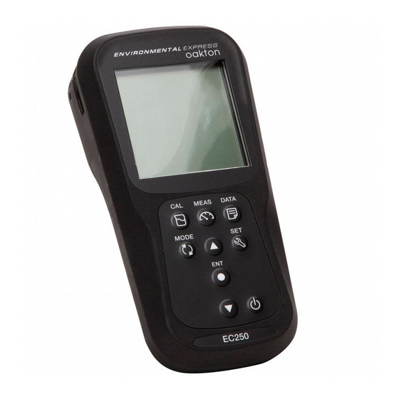
Product overview Product components Name Function Monochrome LCD Displays the measured value Operation keys Used for instrument operation Electrode connector Connect to the BNC connector of the electrode Temperature connector (T) Connect to the temperature sensor of the electrode Battery cover Open/close to insert/remove batteries Electrode holder Hold the electrode to carry with the instrument... - Page 15 Product overview Display Name Function Displays the current operation mode (Setup, Calibration, Status Icon Measurement and Data mode) Displays the measured parameters like COND, Res, TDS and Parameters Stability indicator shows value is stable for the documentation in auto-stable and auto-hold modes Appears when the measured value display is stable and fixed in auto-hold mode Temperature display...
- Page 16 Product overview Battery level display 100% battery life 50% battery life 20% battery life Batteries are weak and need replacement. BATT LOW on page 49 is displayed and operation is disabled Electrode sensitivity level Electrode sensitivity 95% (excellent) Electrode sensitivity between 85% to 95% (very good) Electrode sensitivity between 80% to 85% (good).
- Page 17 Product overview Keypad operation Name Function Switches from the measurement mode to the calibration mode. CAL key Starts calibration in the calibration mode. Switches the operation mode to the measurement mode. MEAS key Releases the fixed measurement value mode in the auto hold mode and begins a new measurement.
-
Page 18: Basic Operations
Basic operations Basic operations This section describes function and basic operation method of each part of OAKTON 200 series Handheld meters. Turning on the instrument Inserting the batteries This instrument is operated by batteries. You can use AA alkaline batteries or AA Ni- MH chargeable batteries. - Page 19 Basic operations Connecting an electrode To perform calibration / measurement, it is necessary to use the appropriate electrode for measurement parameter. Use the following procedure to correctly connect the electrode to the instrument. 1. Insert the electrode connector by fitting its groove with the connector pin of the instrument.
-
Page 20: Mode And Measurement
Basic operations Mode and measurement Changing the operation mode You can change the operation mode to four available modes depending on the purpose of use. The status icon indicates the current mode. Icon Name Function Setup mode Perform various custom. Calibration mode Performs calibration. - Page 21 Basic operations Changing the measurement parameter This instrument measures multiple parameters. For measurement, an electrode corresponding to the measurement parameter is required. In the measurement mode, the measurement parameter can be changed by pressing the key. 1.800.544.2843 www.calcert.com sales@calcert.com...
-
Page 22: Calibration
Conductivity calibration Calibration This section describes the basic calibration method of each measurement parameter using OAKTON 200 series Handheld meters and conductivity electrode. Conductivity Calibration Calibration is necessary for accurate electrical conductivity measurement. To perform conductivity calibration, follow the procedure detailed below: Prerequisites Clean the conductivity electrode with DI (deionized) water and wipe it with tissue paper. - Page 23 Conductivity calibration Calibration Auto calibration 1. After placing the conductivity electrode in the standard solution, press the key. 2. Meter displays Auto cal as per set calibration method and starts measuring various calibration values with a blinking on screen. 3. Wait for the to stabilize (stable calibration reading).
- Page 24 Conductivity calibration Manual calibration 1. After placing the conductivity electrode in the standard solution, press the key. 2. Meter displays Manual cal as per set calibration method and starts measuring various calibration values with a blinking on screen. 3. Wait for the to stabilize (stable calibration reading).
-
Page 25: Tds Calibration
TDS values will be recalibrated accordingly. Set the required TDS curve in OAKTON 200 series Handheld meters. Available TDS curves are; - LINR (Linear factor with adjustable factor from 0.4 to 1.0) -
Page 26: Salinity Calibration
Dip the conductivity electrode in the standard solution till the hole at the upper part of the electrode is immersed. Note Before salinity calibration, set the required salinity method. In OAKTON 200 series Hand- held meters, available salinity methods are; - NACL - SEA.W (Sea water) - Page 27 Conductivity calibration Calibration 1. After placing the conductivity electrode in the standard solution, press the key. 2. Meter starts measuring various calibration values with a blinking on screen. 3. Wait for the to stabilize (stable calibration reading). 4. Use the keys to adjust the salinity value.
-
Page 28: Temperature Calibration
Temperature calibration Temperature Calibration Temperature calibration is required to accurately match the conductivity electrode to the meter. Check the temperature reading and if its acceptable, no temperature calibration is required. If you need to calibrate, please follow the procedure detailed below: Prerequisites Clean the conductivity electrode with DI (deionized) water and wipe it with tissue paper. - Page 29 Temperature calibration Calibration 1. After placing the conductivity electrode in the standard solution, press the key. 2. Press the key to switch to temperature calibration mode. Meter displays measured temperature value. 3. Use the keys to adjust the temperature to the required value. 4.
-
Page 30: Data
Note If the data storage limit reaches 500 in EC250 model or 1000 in EC260 model, memory full error occurs and MEM FULL is displayed. In such case, print the data or transfer necessary data to a PC (only for EC260) and delete the data from the internal memory of the instrument. -
Page 31: Data Transfer
Transfer data to PC Connect the instrument to a PC using phono jack to USB cable to transfer saved data to the PC (for OAKTON EC260 only). Connect the phono jack at the instrument side to the communication port on the PC. -
Page 32: Setup
Select conductivity unit Set calibration mode Set temperature coefficient Set reference temperature Erase calibration data To set the COND functions using OAKTON 200 series Handheld meters, follow the procedure detailed below: Prerequisites Switch on the EC meter. Note Default cell constant value is 1.00 and you can set a value in between 0.070 to 13.00. - Page 33 Conductivity set up P1.1 Cell constant setup 1. Press the key, P1 COND screen appears. 2. Press the ENT key, P1.1 CELL screen appears. 3. Press the ENT key, by default CELL 1.00 appears. 4. Use the keys to set the cell constant in between 0.070 to 13.00. 5.
- Page 34 Conductivity set up P1.2 Select conductivity unit 1. Press the key, P1 COND screen appears. 2. Press the ENT key, P1.1 CELL screen appears. 3. Press the key, P1.2 UNIT screen appears. 4. Press the ENT key, by default UNIT S/cm appears. 5.
- Page 35 Conductivity set up P1.3 calibration mode setup 1. Press the key, P1 COND screen appears. 2. Press the ENT key, P1.1 CELL screen appears. 3. Press the key, P1.2 UNIT screen appears. 4. Press the key, P1.3 A.CAL appears. 5. Press the ENT key, A.CAL ON screen appears with ON as default setup.
- Page 36 Conductivity set up P1.4 Temperature coefficient setup 1.Press the key, P1 COND screen appears. 2.Press the ENT key, P1.1 CELL screen appears. 3.Press the key, P1.2 UNIT screen appears. 4.Press the key, P1.3 A.CAL appears. 5.Press the key, P1.4 T.CFF appears. 6.Press the ENT key, T.CFF 2.00% screen appears.
- Page 37 Conductivity set up P1.5 Reference temperature setup 1.Press the key, P1 COND screen appears. 2.Press the ENT key, P1.1 CELL screen appears. 3.Press the key, P1.2 UNIT screen appears. 4.Press the key, P1.3 A.CAL appears. 5.Press the key, P1.4 T.CFF appears. 6.Press the key, P1.5 T.rEF appears.
- Page 38 Conductivity set up P1.6 Erase calibration data 1.Press the key, P1 COND screen appears. 2.Press the ENT key, P1.1 CELL screen appears. 3.Press the key, P1.2 UNIT screen appears. 4.Press the key, P1.3 A.CAL appears. 5.Press the key, P1.4 T.CFF appears. 6.Press the key, P1.5 T.rEF appears.
-
Page 39: P2 Tds Setup
P2 TDS setup Using P2 TDS setup function of the meter, you can: Select TDS curve Select TDS unit To set the TDS functions using OAKTON 200 series Handheld meters, follow the procedure detailed below: Prerequisites Switch on the EC meter. - Page 40 TDS set up P2.1 TDS curve selection 1. Press the key, P1 COND screen appears. 2. Press the key, P2 TDS screen appears. 3. Press the ENT key, P2.1 FACT screen appears. 4. Press the ENT key, by default FACT LINR appears. 5.
- Page 41 TDS set up P2.2 Select TDS unit 1. Press the key, P1 COND screen appears. 2. Press the key, P2 TDS screen appears. 3. Press the ENT key, P2.1 FACT screen appears. 4. Press the key, P2.2 UNIT screen appears. 5.
-
Page 42: P3 Sal Setup
Using P3 SAL setups function of the meter, you can: Select salinity unit Select salinity curve Erase calibration data To set the salinity functions using OAKTON 200 series Handheld meters, follow the procedure detailed below: Prerequisites Switch on the EC meter. - Page 43 Salinity set up P3.1 select salinity unit 1. Press the key, P1 COND screen appears. 2. Press the key, P2 TDS screen appears. 3. Press the key, P3 SAL screen appears. 4. Press the ENT key, P3.1 UNIT screen appears. 5.
- Page 44 Salinity set up P3.2 select salinity type 1. Press the key, P1 COND screen appears. 2. Press the key, P2 TDS screen appears. 3. Press the key, P3 SAL screen appears. 4. Press the ENT key, P3.1 UNIT screen appears. 5.
- Page 45 Salinity set up P3.3 Erase calibration data 1. Press the key, P1 COND screen appears. 2. Press the key, P2 TDS screen appears. 3. Press the key, P3 SAL screen appears. 4. Press the ENT key, P3.1 UNIT screen appears. 5.
-
Page 46: P4 Data Setup
Set data log interval Set print data log Erase data log To set the data functions using OAKTON 200 series Handheld meters, follow the procedure detailed below: Note Default data log interval is ----, where ---- indicates no data log interval has been set. - Page 47 Data set up P4.1 Data log interval setup 1. Press the key, P1 COND screen appears. 2. Press the key, P2 TDS screen appears. 3. Press the key, P3 SAL screen appears. 4. Press the key, P4 DATA screen appears. 5.
- Page 48 Data set up P4.2 Print data setup 1. Press the key, P1 COND screen appears. 2. Press the key, P2 TDS screen appears. 3. Press the key, P3 SAL screen appears. 4. Press the key, P4 DATA screen appears. 5. Press the ENT key, P4.1 LOG screen appears.
- Page 49 Data set up P4.3 Erase data 1. Press the key, P1 COND screen appears. 2. Press the key, P2 TDS screen appears. 3. Press the key, P3 SAL screen appears. 4. Press the key, P4 DATA screen appears. 5. Press the ENT key, P4.1 LOG screen appears.
-
Page 50: P5 General Setup
Using P5 General setup function of the meter, you can: Select stability mode of the meter Set auto shut-off time Select temperature unit Reset the meter To set the general functions using OAKTON 200 series Handheld meters, follow the procedure detailed below: Prerequisites Switch on the EC meter. Note In the calibration mode, the auto stable (AS) mode is activated.Default stability setup in... - Page 51 General set up P5.1 Auto Stable, Auto Hold and Real Time mode setup Auto Stable (AS) mode - the meter shows live readings annunciator blinks until the reading is stable. Auto Hold (AH) mode - the meter locks the stable reading; annunciator blinks until reading is stable and then lights up.
- Page 52 General set up P5.2 Auto shut-off time setup 1. Press the key, P1 COND screen appears. 2. Press the key, P2 TDS screen appears. 3. Press the key, P3 SAL screen appears. 4. Press the key, P4 DATA screen appears. 5.
- Page 53 General set up P5.3 Temperature unit setup 1. Press the key, P1 COND screen appears. 2. Press the key, P2 TDS screen appears. 3. Press the key, P3 SAL screen appears. 4. Press the key, P4 DATA screen appears. 5. Press the key, P5 GEN screen appears.
- Page 54 General set up P5.4 Reset Meter 1. Press the key, P1 COND screen appears. 2. Press the key, P2 TDS screen appears. 3. Press the key, P3 SAL screen appears. 4. Press the key, P4 DATA screen appears. 5. Press the key, P5 GEN screen appears.
-
Page 55: P6 Clk Setup
Real-time clock functionality is available only for OAKTON 200 series Handheld meters. Using P4 Clock setup function of the meter, you can set: Date Time To set the clock function using OAKTON 200 series Handheld meters, follow the procedure detailed below: Prerequisites Switch on the EC meter. - Page 56 Clock set up P6.1 Date setup 1. Press the key, P1 COND screen appears. 2. Press the key, P2 TDS screen appears. 3. Press the key, P3 SAL screen appears. 4. Press the key, P4 DATA screen appears. 5. Press the key, P5 GEN screen appears.
- Page 57 Clock set up P6.2 Time setup 1. Press the key, P1 COND screen appears. 2. Press the key, P2 TDS screen appears. 3. Press the key, P3 SAL screen appears. 4. Press the key, P4 DATA screen appears. 5. Press the key, P5 GEN screen appears.
-
Page 58: Maintenance And Storage
Maintenance and storage Maintenance and storage This section describes maintenance of OAKTON 200 series Handheld meters, conductivity electrodes used with the meter. Contact for maintenance Please contact your dealer for the product maintenance. Maintenance and storage of the instrument How to clean the instrument If the instrument is dirty, wipe it gently with a soft dry cloth. -
Page 59: Maintenance And Storage Of The Conductivity Electrode
Maintenance and storage Maintenance and storage of the conductivity electrode This section describes an overview of the procedures for maintenance and storage of conductivity electrode. How to clean the electrode Always clean the electrode with deionized water after every measurement. When the response is slow or residue from the sample adheres to the electrode, use the appropriate method below to clean the electrode, and then clean again with deionized water. -
Page 60: Error Messages And Trouble Shooting
Error messages and trouble shooting Error messages and trouble shooting Error message This section describes the causes of typical errors and the actions to be taken to resolve respective errors. If ERR is displayed while you are using the instrument, check the error, its cause and action to be taken in the error list below. - Page 61 Error messages and trouble shooting Troubleshooting his section describes causes and actions to take for problems that customers frequently ask. The indicated value fluctuates < Problem with the electrode > Cause How to solve problem The conductivity electrode is dirty. Clean the conductivity cell.
- Page 62 Error messages and trouble shooting The indicated value does not change/No response Cause How to solve problem The conductivity electrode is broken. Replace the conductivity cell. The conductivity electrode is not Connect the conductivity electrode properly. connected correctly. The instrument is in HOLD state. Cancel the HOLD state.
- Page 63 Error messages and trouble shooting Swelling of keypad Cause How to solve problem To eliminate the pressure difference between the Using the instrument at high inside and outside of the instrument, briefly open elevation or other location where the and then close the serial cable cover. After opening, air pressure is different from sea correctly close the cover to maintain dust and water level.
-
Page 64: Appendix
Technical note Appendix Appendix 1 This section describes technical information and option for OAKTON EC200 handheld meters. Conductivity standard values at various temperatures Temp. Conductivity value at 25°C (°C) 84 ( S/cm) 1413 ( S/cm) 12.88 (mS/cm) 111.8 (mS/cm) 7.15 65.4... - Page 65 Printout summary Appendix 2 Printer format - Measurement Conductivity Meter Model : OAKTON EC260 Serial Number : 123456789 SW Revision : 1.00 Date : 20 Aug 2018 Time : 10:10:28 Mode : Conductivity Cond : 1413.uS/cm Temperature : 25.0 C (MAN)
- Page 66 Printout summary Salinity Meter Model : OAKTON EC260 Serial Number : 123456789 SW Revision : 1.00 Date : 20 Aug 2018 Time : 10:10:28 Mode : Salinity Salinity : 50.0 ppt Temperature : 25.0 C(MAN) Electrode Status : Excellent User Name...
- Page 67 Printout summary Printer format - Data log Meter Model : OAKTON EC260 Serial Number : 123456789 SW Revision : 1.00 User Name Signature Logged Data Location Date : 10 Aug 2018 Time : 10:10:28 Mode : pH : 7.00 pH : 0.0 mV...
- Page 68 Printout summary Printer format - Calibration Meter Model : OAKTON EC260 Serial Number : 123456789 SW Revision : 1.00 Date : 20 Aug 2018 Time : 10:10:28 Calibration data Cal Date : 20 Jun 2018 Cal Time : 10:10:10 Cal Points : 84.0 uS.
- Page 69 Specifications Appendix 3 EC250 EC260 Model EC/TDS/Res/Sal/Temp (°C/°F) Conductivity Range µS/cm to 200.0 mS/cm (k=1.0) Resolution 0.05% full scale Accuracy ±0.6% full scale, ±1.5% full scale > 18.0 mS/cm Reference Temperature 15 to 30 °C (adjustable) Temperature Coefficient 0.00 to 10.00 %/°C Cell Constants 0.1, 1.0, 10.0...
- Page 70 Specifications PC Communication Printer Communication Meter Inputs BNC, phono Display Custom LCD with backlight Housing IP67, shock & scratch resistant, non-slip Power Requirement 2 × AA batteries Battery Life > 500 hours Dimensions 160 (L) × 80 (W) × 40.60 (H) mm Approx.
- Page 71 Specifications Table of conductivity cell range Unit: S/m Cell constant Range 1000 m 100 m 10 m 20.0 to 200.0 S/m 2.00 to 19.99 S/m 0.200 to 1.999 S/m 20.0 to 199.9 mS/m 2.00 (0.00) to 19.99 mS/m 0.200 (0.000) to 1.999 mS/m 0.0 to 199.9 µS/m Unit: S/cm Cell constant...
- Page 72 Specifications Table of conductivity cell range (resistivity range) Unit: Cell constant Range 10 m 100 m 1000 m 0.200 to 2.000 M 20.0 to 199.9 k 2.00 to 19.99 k 0.200 to 1.999 k 20.0(0.0) to 199.9 2.00(0.00) to 19.99 0.000 to 1.999 Unit: Cell constant...
- Page 73 1.800.544.2843 www.calcert.com sales@calcert.com...
Need help?
Do you have a question about the EC250 and is the answer not in the manual?
Questions and answers