Dimplex XLF50 Manual
Hide thumbs
Also See for XLF50:
- Installation and user manual (72 pages) ,
- Owner's manual (68 pages) ,
- Service manual (18 pages)

Related Manuals for Dimplex XLF50


Summary of Contents for Dimplex XLF50
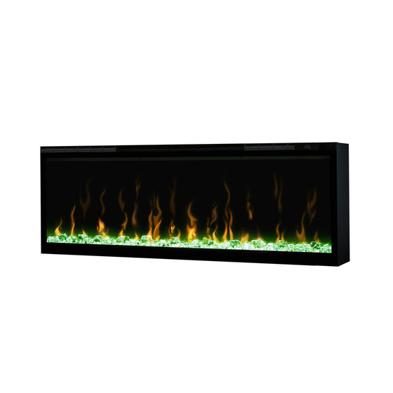
- Page 1 Owner’s Manual Model XLF50 XLF60 XLF74 XLF100 IMPORTANT SAFETY INFORMATION: 7215520100R02...
-
Page 2: Table Of Contents
Table of Contents Framing Permanent Heat Disable Bathroom Use Final Assembly Wiring Diagrams Operation Warranty NOTE: CAUTION: WARNING:... - Page 3 Welcome & Congratulations www.dimplex.com/register Model and Serial Number Label Please carefully read and save these instructions. CAUTION: NO NEED TO RETURN TO THE STORE Questions with operation or assembly? Require Parts Information? Contact us at: www.dimplex.com/customer_support Toll-Free 1-888-346-7539 In order to better serve you, please have your model and serial number...
- Page 4 IMPORTANT INSTRUCTIONS Do not operate the unit after may fall into a bathtub or other The trim around the heater DANGER: High temperatures Do not insert or allow foreign or exhaust opening as this may when any heater is used by and whenever the unit is left operating and unattended supervised to ensure that they...
- Page 5 IMPORTANT INSTRUCTIONS Use this heater only as WARNING: WARNING: Do not install Do not burn wood or other NOTE: approved by the party before performing any When transporting or storing vibration and store so as to CAUTION DO NOT OPEN SAVE THESE INSTRUCTIONS...
- Page 6 60.31 in [1532 mm] XLF74 74.31 in [1887 mm] XLF100 100.31 in [2548 mm] 4.34 in. 110 mm XLF50 51.41 in [1306 mm] XLF60 61.41 in [1560 mm] 5.79 in. XLF74 75.41 in [1941 mm] 147 mm XLF100 101.41 in [2576 mm]...
-
Page 7: Framing
Fireplace Installation CAUTION: Ensure installation NOTE: Leave the front glass vapor barrier or insulation and safely in the box until the time NOTE: Framing CAUTION: Two people will be fuse blows on a regular basis required for various steps of this This design of this unit allows partial recess sub-surface... - Page 8 Fireplace Installation Installation Recommendations To frame the fireplace: with Overhanging Surfaces Prepare a wall with a framed Figure 2 provides the overhang • Solid gray box ( • of the unit to allow the power supply wires to easily be run •...
- Page 9 Fireplace Installation NOTE: Figure 4 that the bottom of the unit from the ground to maintain an optimized viewing angle of the WARNING: Do not attempt WARNING: Make sure the to be installed has the power The unit is provided with an Drive four supplied mounting supply power wire through a...
-
Page 10: Permanent Heat Disable
Fireplace Installation Figure 5 Flame Panel Mounting Holes Permanent Heat Disable Figure 6 permanently disabled by the heater before any other To disable the heater: HT EN... - Page 11 Fireplace Installation Electrical 120V Installation - Wall Switch 120V Installation - Direct NOTE: Wire CAUTION: Use the appropriate rated for a minimum of CAUTION: Use the appropriate To 120V direct wire: To wire through a wall switch: to the live wire from the power to the live wire from the main unit to the neutral wire from the unit to the ground wire from the...
- Page 12 Fireplace Installation Figure 7 WHITE - N WHITE – N 120 V BLACK – L1 BLACK – L POWER WALL SUPPLY SWITCH (BREAKER GROUND - G GROUND - G PANEL) Feed wire from plug kit into and do not protrude past the 120V Installation - Plug Kit WARNING: This heater is not intended for use with an...
- Page 13 Fireplace Installation Figure 8 240V Installations CAUTION: Use the appropriate unit to the ground wire from the power supply with a wire nut To 240V direct wire: unit to the L1 wire from the and do not protrude past the unit to the L2 wire from the unit to the neutral wire from the...
-
Page 14: Final Assembly
Fireplace Installation For Bathroom Use If this unit is installed in a into the openings on either side Tip the glass into the unit and where it may fall into a bathtub or Final Assembly of the media tray (for optimum pour and evenly distribute the smaller media into the Tip the front glass into the... - Page 15 Fireplace Installation Figure 9 Openings Media Tray Figure 10...
-
Page 16: Wiring Diagrams
Wiring Diagram Figure 11 Figure 12A XLF50 CERAMIC ELEMENT MAIN CONTROL BOARD THERMAL CUTOUTS THERMISTOR POWER ADAPTER FLICKER MOTOR FLAME LED ASSEMBLY MEDIA LED ASSEMBLY MEDIA LED ASSEMBLY... - Page 17 Wiring Diagram Figure 12B XLF60 CERAMIC ELEMENT MAIN CONTROL BOARD THERMAL CUTOUTS THERMISTOR POWER ADAPTER FLICKER MOTOR FLAME LED ASSEMBLY MEDIA LED ASSEMBLY MEDIA LED ASSEMBLY Figure 12C XLF74, XLF100 CERAMIC ELEMENT MAIN CONTROL BOARD THERMAL CUTOUTS THERMISTOR POWER ADAPTER FLICKER MOTOR RELAY BOARD POWER ADAPTER...
-
Page 18: Operation
Operation ! NOTE: The element retains General Operation WARNING: firebox must be properly period before the fan shuts off Remote Operation fan speed and heater wattage to requirements of the room based ! NOTE: Controls to maintain the desired room Standby Standby button on the remote temperature drops and requires... - Page 19 Operation Figure 13 Figure 14 A C D E H Display ! NOTE: When any button is pressed on the unit the intake temperature will be displayed on vated by pressing the ! NOTE: After the heater is Heat ON/OFF ! NOTE: button on the remote or the operated in Heat Only Mode...
- Page 20 Operation ! NOTE: The heater may emit set point will be displayed for heating of internal heater parts Temperature Down ! NOTE: Holding the buttons down for manual controls Adjusted by repeatedly • Eco Operation temperature on the Display Adjusted by pressing the the amount of heat being •...
- Page 21 Operation • • preset light settings of the Disable Heat ! NOTE: Two of the themes in stops Pressing the buttons on the manual controls at the same time and holding for 2 will disable and enable Brightness ! NOTE: When the heater has been disabled and any of the Adjusted by repeatedly pressing If the Permanent Heat Disable...
- Page 22 Operation Resetting the Temperature Sleep Timer after a preset time (from 30 To set the timer press the • The Display will display the and waiting 5 minutes before CAUTION: If you need to pressing the button will display the time remaining ! NOTE: by pressing the button...
- Page 23 Maintenance Remote Control Battery Partiall Replacement Cleaning WARNING: Fireplace Surface Cleaning NOTE: Servicing not be operated with an a build up of heat and eventual...
- Page 24 Warranty IGNITEXL™ 5 YEAR LIMITED WARRANTY Section 1 Products to which this Limited Warranty Applies responsible for all labor and transportation This Limited Warranty applies to your newly not allow limitations on how long an implied This Limited Warranty applies only to Section 4 What this Limited Warranty Does Not Cover Northwest Territories or in any of the...
- Page 25 Warranty How State and Provincial law(s) apply for installation or removal of the surrounds Section 6 When Glen Dimplex Americas and its Dealers and Service Agents are not Liable...
- Page 26 Technical Support...
Need help?
Do you have a question about the XLF50 and is the answer not in the manual?
Questions and answers