Table of Contents
Advertisement
Quick Links
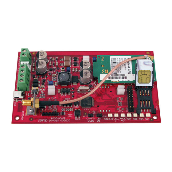
Conettix ITS-DX4020-G
GPRS/GSM IP Communicator
Quick Start Guide
For complete installation, confi guration, and testing instructions,
refer to the Conettix ITS-DX4020-G Installation and Operation
Guide (P/N: F01U133268) provided on the supplied CD-ROM.
Control Panel Compatibility
DS7200V2 Series
Version 2.10 or later
DS7400XiV4
Version 4.10 or later
FPD-7024
All versions
Easy Series
Version 3.0 or later
GV2 Series
D9412GV2, D7412GV2, D7212GV2
GV3 Series
D9412GV3, D7412GV3, D7212GV3
GV4 Series
D9412GV4, D7412GV4, D7212GV4
ICP-CMS6-CHI
ICP-CMS8-CHI
1
1
Disconnect the Power
Before installing the ITS-DX4020-G, disconnect
all power to the control panel (AC and standby
battery).
2
2
Insert the SIM Card
1. Open the SIM card holder.
2. Insert the SIM card into the card guide.
3. Close the SIM card holder.
MODELO: ITS-DX4020-G
2113-12-5164
( 0 1 ) 0 7 8 9 1 0 0 9 5 3 8 4 7 1
Certifi cations
ANATEL
No. 2113-12-5164
Australia
A-Tick Approved
CE
- EN60950 Safety
- EN50130-4 Electromagnetic Compatability
- EN55022 Radiated/Conducted Emissions
INCERT
No. B-509-0005/d
Norwegian
FGI: T-127/09, ATS4, grade 3
3
3
Mount the ITS-DX4020-G
1. Mount the ITS-DX4020-G on the control panel
enclosure using the supplied mounting screws.
Use any of the standard three-hole mounting
patterns on the control panel enclosure. If
necessary, remove the three mounting knockouts.
2. Mount the magnetic antenna to a metallic surface.
3. Connect the antenna cable to the threaded
ANTENNA connector on the ITS-DX4020-G.
4
4
Connect to the Control Panel
Connect the ITS-DX4020-G to the control panel as shown below.
Dual Wireless Mode (IP over GPRS and Contact ID over GSM): Easy Series
•
•
IP over GPRS Mode: All compatible control panels
PSTN (Contact ID) over GSM: DS7200V2, DS7400XiV4, Easy Series, FPD-7024, GV3 Series, GV4 Series, ICP-CMS8-
•
CHI, ICP-CMS6-CHI
DS7200V2 Series
DS7400XiV4
Easy Series
FPD-7024
GV2 Series
GV3 Series
GV4 Series
ICP-CMS6-CHI
ICP-CMS8-CH
NOTE: For Dual Wireless Mode, use the PSTN (Contact ID) over GSM Mode fi gure, but include all four data bus wires.
5
5
Apply Power
Connect power to the system (AC and standby battery).
6
6
Check Signal Strength
Check the signal strength LEDs (SS1, SS2, and SS3).
•
If signal strength is acceptable, you are ready to confi gure the ITS-DX4020-G.
•
If signal strength is unacceptable, check the site for possible causes of signal interference.
NOTE: Depending on the SIM card used, fi rst-time registration might take up to 3 minutes to complete. When the SIM
card registration is complete, the signal strength LEDs will light.
SS1
SS2
SS3
SS1
SS2
SS3
SS1
SS2
SS3
SS1
SS2
SS3
SS1
SS2
SS3
PSTN (Contact ID) over GSM Mode
R
RH
TH
(+)
(-)
T
ITS-DX4020-G
=
www.boschsecuritysystems.com
=
=
=
© 2012 Bosch Security Systems, Inc.
=
2012.10
F01U274446-02 en
B
G
Y
R
DS7200V2 Series
DS7200V2 Series
DS7400XiV4
DS7400XiV4
Easy Series
FPD-7024
Easy Series
GV3 Series
FPD-7024
GV3 Series
GV4 Series
1
Advertisement
Table of Contents

Related Manuals for Bosch ITS-DX4020-G


Summary of Contents for Bosch ITS-DX4020-G
- Page 1 Check the signal strength LEDs (SS1, SS2, and SS3). 2. Insert the SIM card into the card guide. • If signal strength is acceptable, you are ready to confi gure the ITS-DX4020-G. 3. Close the SIM card holder. • If signal strength is unacceptable, check the site for possible causes of signal interference.
- Page 2 Test the ITS-DX4020-G You can confi gure the ITS-DX4020-G by sending a text message from your mobile phone or by using the USB interface from a PC or laptop. Contact the central monitoring station for destination IP address and port number settings. Provide SMS (Text Message) Confi...
Need help?
Do you have a question about the ITS-DX4020-G and is the answer not in the manual?
Questions and answers