Advertisement
Quick Links
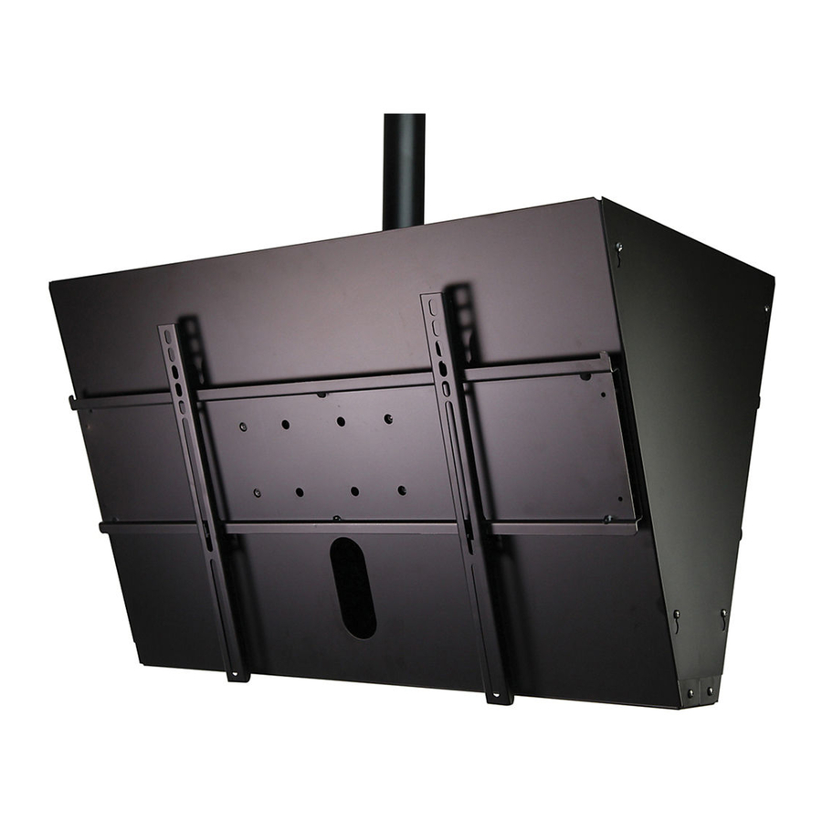
Installation and Assembly: Back to Back Ceiling Mount
Model: DST965
* SEE NOTE
* NOTE: DST965 WILL NOT WORK WITH ADJUSTABLE
Maximum Load Capacity: 300 Ib (136 kg)
EXTENSION COLUMNS AEC006009, OR AEC012018
2300 White Oak Circle • Aurora, IL 60502 • (800) 865-2112 • Fax: (800) 359-6500 • www.peerless-av.com
ISSUED: 10-24-11 SHEET #: 125-9260-3 03-17-14
Advertisement

Related Manuals for peerless-AV DST965


Summary of Contents for peerless-AV DST965
- Page 1 * NOTE: DST965 WILL NOT WORK WITH ADJUSTABLE Maximum Load Capacity: 300 Ib (136 kg) EXTENSION COLUMNS AEC006009, OR AEC012018 2300 White Oak Circle • Aurora, IL 60502 • (800) 865-2112 • Fax: (800) 359-6500 • www.peerless-av.com ISSUED: 10-24-11 SHEET #: 125-9260-3 03-17-14...
-
Page 2: Parts List
Before you start make sure all parts listed are included with your product. PARTS LIST Description Qty. Part # A main cover 145-1452 B side cover 145-1453 C cable assembly 600-0033 D adapter bracket 202-1655 component shelf clamp 145-1180 bottom bracket 145-1454 G component shelf 145-1179... - Page 3 Some parts may appear slightly different than illustrated. Security Adapter Bracket Fasteners M4 x 12 mm (12) M6 x 12 mm (8) M5 x 12 mm (8) 510-1079 M8 x 15 mm (12) 520-1050 520-1064 M6 x 20 mm (8) 520-1068 M5 x 25 mm (8) 520-9554...
- Page 4 Note: Notch indicates bottom of interface bracket (O) as shown in detail 1. Slide interface bracket (O) onto adjustable extension column (not supplied) and attach using fi ber washer (V) and retaining collar (W) as shown in fi gure 1.1. Carefully thread retaining collar (W) onto end of extension column.
- Page 5 Screw eight M10 x 15 mm penta-pin screws (Q) into interface bracket (O) leaving approximately 1/4" of exposed thread as shown below and in detail 3. 1/4" Detail 3 Attaching Component Shelf Secure two component shelves (G) to adjustable extension column (not supplied) using two component shelf clamps (E) and four 1/4-20 X 2"...
- Page 6 Secure four M10 x 15 mm penta-pin screws (Q) through cable bracket (K), tilt plate (P), main cover (A), and adapter plate (M), and as shown below. Repeat with second support assembly. Hook tilt plate (P) and support assembly onto M10 x 15 mm penta-pin screws (Q). Repeat with second support assembly.
- Page 7 Run cable assembly (J) down through extension column around and through two cable brackets (K) as shown below. Secure cable to itself using u-bolt, clamp and nuts from cable wire clamp (J). CABLE U-BOLT CLAMP Secure bottom bracket (F) to support assemblies using M5 x 10 mm socket pin Type F screws (H) as shown below.
-
Page 8: Installing Adapter Brackets
Installing Adapter Brackets WARNING • Tighten screws so adapter brackets are fi rmly attached. Do not tighten with excessive force. Overtightening can cause stress damage to screws, greatly reducing their holding power and possibly causing screw heads to become detached. Tighten to 40 in. • lb (4.5 N.M.) maximum torque. •... - Page 9 For Flat Back Screen Begin with the shortest length screw, hand thread through multi-washer and adapter bracket into screen as shown below. Screw must make at least three full turns into the mounting hole and fi t snug into place. Do not over tighten.
-
Page 10: Mounting And Removing Flat Panel Screen
Mounting and Removing Flat Panel Screen WARNING • Always use an assistant or mechanical lifting equipment to safely lift and position the plasma television. Hook adapter brackets (D) onto adapter plate (M), then slowly swing screen in as shown. Turn safety/security screws clockwise at least six times to prevent screen from being removed as shown in detail 5. - Page 11 Secure PC component to component shelf (G) Thread four M5 x 10 mm socket pin Type F screws with safety belt (L) through slots on component (H) into support assemblies leaving 1/8" of exposed shelf (G) using instructions provided with thread.
Need help?
Do you have a question about the DST965 and is the answer not in the manual?
Questions and answers