Table of Contents
Advertisement
Quick Links
Advertisement
Table of Contents

Related Manuals for JRC Alphatron AlphaPilot MFS


Summary of Contents for JRC Alphatron AlphaPilot MFS
- Page 1 AlphaPilot MFS Operation Manual www.alphatronmarine.com...
-
Page 2: Table Of Contents
Contents Preface............................4 Revision History ..........................5 Glossary ............................6 Abbreviations ..........................6 Definitions ...........................7 Safety Information ........................11 III. Warranty........................... 13 IV. About the manual ........................14 Intended readers ........................... 14 Manual overview ........................... 14 Introduction ..........................15 AlphaPilot MFS Control Unit ...................... 17 Operating modes ........................ - Page 3 Autotrim ..........................27 Rudder-Thruster modes ..................... 28 Alert handling ........................28 Dimming ..........................28 Remote control ......................... 28 Alarm test .......................... 29 Menus ............................30 Menu ‘Main Menu’ ......................30 5.1.1 Touch screen calibration .................... 31 5.1.2 Display cleaning ......................33 5.1.3 Theme ........................
-
Page 4: Preface
Preface The Alphatron AlphaPilot MFS is a type approved Heading Control System (i.e. Autopilot) with self- adjusting ‘Auto Tune’ algorithm, designed to fit vessels of any size, including high speed crafts. It is a modern and technologically advanced digital vessel control unit that is intended to reduce the operator’s workload, increase the vessel motion efficiency and improve operational safety. -
Page 5: Revision History
Revision History Revision Date Description Author 02-12-2020 First issue J. Kreeft 18-02-2021 Completeley updated Appendix A. Removed MFS J. Kreeft model. 19-02-2021 Additional updates on Appendix A. Minor textual J. Kreeft updates. 5 | Introduction... -
Page 6: Glossary
Glossary The glossary contains a list of abbreviations and a list of definitions. Abbreviations Abbreviations as used in this manual are explained in the table below. Abbreviation Description AUTO Automatic (‘Heading Control mode’) Automatic Permanent Helm Course Comparator Alarm Course over ground Digital Nautical Charts ECDIS Electronic Chart Display and Information System... -
Page 7: Definitions
Definitions The meaning of standard definitions as used in this manual are explained in the table below. Definition Description Alert Announcement of abnormal situations and conditions requiring attention. Alerts are divided in four priorities: emergency alarms, alarms, warnings, and cautions: - Emergency alarm: Highest priority of an alert. - Page 8 Definition Description Autopilot A Heading Control System. COG (Course Over COG is the actual direction of progress of a vessel, between two Ground) points, with respect to the surface of the earth. The vessel’s heading may differ from the COG because of wind, tide and currents. Course A vessel's course is the cardinal direction along which the vessel is to be steered.
- Page 9 Definition Description Line between two waypoints defining the track. Main steering gear The machinery, rudder actuators, steering gear power units, if any, and ancillary equipment and the means of applying torque to the rudder stock (e.g. tiller or quadrant) necessary for effecting movement of the rudder for steering the vessel under normal service conditions.
- Page 10 Definition Description Track Control systems must be interfaced with an electronic position fixing system. SOLAS Regulation 19, 2.8.2 requires Heading Control or Track Control Systems to be fitted to all vessels of 10000 GT and upward. There is no requirement to fit a Track Control system to any class of vessel.
-
Page 11: Safety Information
Safety Information The signal words DANGER, WARNING and CAUTION used in this manual indicate the degree of hazard that may be encountered by the user. These words are defined as follows: DANGER Indicates a hazardous situation which, if not avoided, will result in death or serious injury. - Page 12 Immediately turn off the power and disconnect the power supply cable if the equipment is generating any smoke or odour or is overheated. WARNING Immediately inform your local service agent of the symptom to have it repaired. Prolonged equipment operation under such a condition can cause a fire or electric shock.
-
Page 13: Warranty
III. Warranty To not to adversely affect the warranty, the following notices must be adhered to. Operating personnel must not remove equipment covers. Only personnel trained NOTICE and certified by ALPHATRON MARINE must make component replacement and internal adjustment. Do not disassemble or modify the equipment. Failure to observe this instruction NOTICE may cause equipment failure, and it will void the warranty. -
Page 14: About The Manual
Manual overview This manual has the following chapters: • Introduction contains a description of the Alphatron AlphaPilot MFS system. • AlphaPilot MFS Control Unit contains a description of the Control Unit and its interface. • Operating modes contains a description of the autopilot operating modes. -
Page 15: Introduction
The AlphaPilot MFS Control Unit works in conjunction with the AlphaPilot MFS Distribution Unit, which connect to the steering system or to the steering gear. Refer to the Alphatron AlphaPilot MFS Installation manual for more details about the Distribution Unit. - Page 16 MED/4.40 Heading Control System (HCS) for High Speed Craft (HSC): - SOLAS 74 Reg. X/3 - IMO Res.MSC.36(63)-(1994 HSC Code) 13 - IMO Res.MSC.97(73)-(2000 HSC Code) 13 - IMO Res.A.694(17) - IMO Res.A.822(19) - IMO Res.MSC.191(79) - IMO Res.MSC.302(87) - IMO MSC.1/Circ.1349 ‘Fail-to-safety’...
-
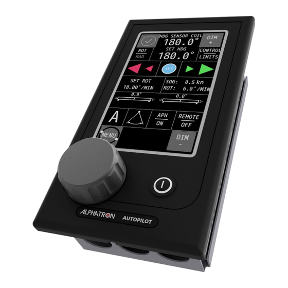
Page 17: Alphapilot Mfs Control Unit
2 AlphaPilot MFS Control Unit The AlphaPilot MFS Control Unit has a touch screen display, rotary knob, and a ON/OFF button. The touch screen display shows information such as heading, current mode and settings, and alerts. The touch screen display is also used to set parameters (see on page 18). - Page 18 example to highlight generic information. For information displayed in a specific operation mode, refer to the respective section (see section ‘Operating modes’ on page 21). Increase Compass Actual Alert symbol brightness source heading level Set ROT or RAD mode CONFIRM/SET LEFT RIGHT Source for...
- Page 19 Item Description Actual heading Actual heading taken from compass source. Actual ROT or RAD value Actual operating ROT or RAD value. Operating ROT value is shown in degrees per minute. Operating RAD value is shown in nautical miles. ROT value can be received from sensor (i.e. ROT:S) or it can be calculated (i.e.
- Page 20 Item Description REMOTE ON/OFF Button to allow or not allow remote control. AlphaPilot MFS Control Unit #2 or #3 (as appropriate) request for system control will been denied when the Master station (e.g. AlphaPilot MFS Control Unit No.1) has been nominated and the REMOTE button of AlphaPilot MFS Control Unit #1 has not been activated.
-
Page 21: Operating Modes
3 Operating modes 3.1 Introduction The operating modes are displayed on the AlphaPilot MFS Control Unit (see on page 18) and Figure 2 explained in this section. Symbols are used to clearly indicate the active autopilot operating mode. To enable a heading control mode, press the MODE|AUTO button to change the control mode (the identifier of the next available control mode appears on the display). -
Page 22: Standby (S) Mode
3.2 Standby (S) mode Autopilot is not operating for vessel heading control. In this mode, the AlphaPilot MFS Control Unit tracks and displays Actual Heading, Rate of Turn (ROT) and Rudder Angle etc. and will continue in a tracking mode until the Autopilot is engaged. The Autopilot can be switched OFF at any time by a continuous two seconds NOTICE ON/OFF button operation. -
Page 23: Enable Auto (A) Control Mode
The following information is displayed in Auto (A) control mode: actual heading, pre-set heading, actual speed, actual ROT in degrees per minute or actual RAD in nautical miles, rudder(s) order, rudder(s) feedback, and steering method. NOTE: While in Auto (A) control mode, the system continuously checks for the availability and quality of heading and speed information. - Page 24 3.4.3.2 Enable or disable Adaptive control The Alphatron AlphaPilot MFS is Speed Adaptive and – provided it is used in Adaptive Mode and calibrated for the correct vessel type (DISP or HSC) – will automatically set its own control parameters for optimum steering performance. In most cases, Adaptive Mode will be preferred.
-
Page 25: Track (T) Control Mode
3.5 Track (T) control mode 3.5.1 Introduction Track (T) control mode (also referred to as ‘Track steering’) combines an ECDIS with the Autopilot. The navigator can program a voyage plan into the ECDIS that contains one or more tracks. The TCS (Track Control System) is used together with the input from the sensors for position, course and speed and is designed to keep the vessel on the plotted route. -
Page 26: Dodge (D) Control Mode
3.6 Dodge (D) control mode 3.6.1 Introduction Short-term manual FU steering (set angle of rudder(s)) via external Dodge controller. Dodge control mode operation is available when the Autopilot is in Auto (A) control mode or in Track (T) control mode. NOTE: Dodge (D) control mode may not be available, as it can be enabled or disabled (see AlphaPilot MFS Installation Manual). -
Page 27: Controls And Functions
4 Controls and functions This section describes other controls and functions (not related to operating modes as described in the previous section). 4.1 Turn on To turn on the AlphaPilot MFS Control Unit, push the ON/OFF button. The AlphaPilot MFS system will start-up (and performs system testing). After start-up, the AlphaPilot MFS system will go into Standby (S) mode (the AlphaPilot is not operating for vessel heading control). -
Page 28: Rudder-Thruster Modes
Factory default setting is AUTOTRIM active (ON) when the Autopilot is switched from STANDBY to ON. (ii) To switch the Autotrim feature OFF, use the APH ON/OFF button (Autotrim will automatically revert to the active state when the Autopilot is switched OFF and ON again). (iii) Single press the APH ON/OFF button to switch Autotrim ON again. -
Page 29: Alarm Test
4.9 Alarm test Generate an alarm for testing purpose. See ‘Alarm test’ at section ‘Menu ‘Main Menu’’ on page 30. 29 | Controls and functions... -
Page 30: Menus
5 Menus The AlphaPilot MFS has generic and advanced settings. All users are authorized to use the generic settings. Only a commissioning engineer has access to the advanced settings (ADV SET and ALPHAPILOT button), which are only needed during commissioning or troubleshooting. All menu items are explained in the following subsections. -
Page 31: Touch Screen Calibration
Menu item Description THEME To change contrast brightness (i.e. illumination) and to set the language. DATE TIME To change the date and/or time. ABOUT The show the name and version of the software and when it was built. ADV SET To change Advanced settings of the AlphaPilot MFS Control Unit. - Page 32 Calibrate the screen by performing the following procedure: 1. Press the CONFIRM CALIBRATE THE TOUCH SCREEN button. The calibration screen appears with text requesting to touch the four numbered reference points that appear on the screen. 2. Touch the four reference points in sequence 1 to 4, as they light up. The application will determine whether the sequence is carried out correctly.
-
Page 33: Display Cleaning
5.1.2 Display cleaning Figure 7: Menu item ‘Display cleaning’ The purpose of the Clean Mode feature is to clean the surface of the touch screen without accidentally activating a function. When the Clean mode is started, the touch screen will be deactivated for 60 seconds. -
Page 34: Theme
5.1.3 Theme Figure 8: Menu item ‘Theme’ 5.1.3.1 Contrast brightness Contrast brightness can be easily adjusted to Day, Dusk and Night settings. To change the contrast brightness, perform the following procedure: 1. Press the + or – button to select the desired ILLUMINATION value. Three different illumination pre-sets can be selected, in accordance with ambient light: DAY, DUSK and NIGHT. -
Page 35: Date And Time
5.1.4 Date and time Figure 9: Menu item ‘Date and time’ To change the date and/or time, perform the following procedure: 1. Press the + and/or – button to set the correct DATE values. 2. Press the > button to select the TIME screen. 3. -
Page 36: Alarm Test
5.1.6 Alarm test Figure 10: Menu item ‘Alarm test’ The purpose of the Alarm Test feature is to let the user verify whether the alert handling is working correctly or not. To start an Alarm Test, perform the following procedure: 1. -
Page 37: Alarms, Warnings, And Cautions
6 Alarms, warnings, and cautions The AlphaPilot MFS system is comprehensively equipped with alarm mechanisms that continuously monitor the operational integrity of a wide range of functions from heading input data to steering gear response. Alarms, warnings, and cautions are displayed on the AlphaPilot MFS Control Unit. An Alert symbol will be shown, accompanied with or without an audible signal. - Page 38 The following alert indicators are applicable: Symbol Symbol Audible signal Status Priority behaviour Three short audible Alarm active, signals, Flashing High repeated within every acknowledged 10 s Alarm active, Flashing Silent silenced One short audible signal, Warnings active, Flashing repeated within every 5 min or replaced by acknowledged an alarm...
- Page 39 Alarm The situation requires an immediate response, or the Autopilot system will go out-of-order. Warning The system has degraded, but it still functions. It is possible to reduce the quality of control. A response to this message is required. Caution The system does not require an immediate reaction and informs about the degradation of the system without deterioration of the quality of management.
-
Page 40: Appendices
Appendices 40 | Alarms, warnings, and cautions... -
Page 41: Appendix A: Alphatron Mfs Alerts
Appendix A: Alphatron MFS Alerts Alert display messages and BAM alert types Alert Text Message Text BAM Alert Type No alert None Lost HDG control HCS Failed. Switch to Manual steering Alarm Doubtful heading Deviation between heading sources exceeded limit Warning / Alarm Doubtful heading Heading monitor function is impossible... - Page 42 Lost HDG control The BAM alarm “Lost HDG control: HCS Failed. Switch to Manual steering” will be shown if one or more of the following failure conditions occur when the Autopilot is engaged: Internal Distribution unit failure*. ii) Internal Distribution Unit +7V failure*. iii) Internal Distribution Unit +3.5V failure*.
- Page 43 HCS power fail In the event of Main Power supply failure, the BAM caution “HCS Power fail: HCS working normally on Backup Power only” message will be displayed on the Control Unit. ii) In the event of Back Up power supply failure, the BAM caution “HCS Power fail: HCS working normally on Main Power only”...
- Page 44 The Autopilot Set Up Data is stored in the Distribution Unit non-volatile memory and read at power up. The integrity of this data is verified when read and will only be used if no errors are detected. A checksum is included to guard against corrupted data being used.
- Page 45 HDG in Fallback: Step HDG lost, normal HC using Gyro 1 HDG in Fallback: Step HDG lost, normal HC using Gyro 2 HDG in Fallback: Step HDG lost, normal HC using Mag compass HDG in Fallback: Gyro 1 lost, normal HC using Gyro 2 HDG in Fallback: Gyro 1 lost, normal HC using Mag compass HDG in Fallback: Gyro 1 lost, normal HC using Step HDG HDG in Fallback: Gyro 2 lost, normal HC using Gyro 1...
-
Page 46: Operational Alarms
Operational Alarms REM STR ON This alarm occurs if a AlphaPilot MFS Control Unit REMOTE ON/OFF button is operated to enable Remote Controls when a proprietary Remote Power Steer Control is already in an ON condition (REMOTE ON/OFF button action is suspended in this case and prevents inadvertent rudder application due to remotely located Power Steer Unit demands). -
Page 47: Diagnostic Failure Messages: Heading Sensors
Diagnostic failure messages: Heading Sensors CPS HI FAIL Signal from HSC is too large. CPS LO FAIL Signal from HSC too low. CPS PHS FAIL Signals from the 3 sense lines not consistent. COMPASS FAIL High ROT/Rate of change. HDT 1 FAIL Channel 1 input. -
Page 48: Diagnostic Failure Messages: Miscellaneous
HDT 2 FAIL Channel 2 Input. Ditto HDT 1 FAIL. HDG 2 FAIL Channel 2 Input. Ditto HDG 1 FAIL. HDM 2 FAIL Channel 2 Input. Ditto HDM 1 FAIL. HCC 2 FAIL Channel 2 Input. Ditto HCC 1 FAIL. NO NMEA H`DG IN This alarm condition confirms that no NMEA heading data of any type is being received by the AlphaPilot MFS system. -
Page 49: Ethernet Alarms
iii) Rudder at maximum limit as defined by limit switch settings. NOTE: An open circuit limit switch (whether due to adjustment or defect) is signalled by the L/SW OPEN alarm. iv) No rudder demand outputs from AlphaPilot MFS Control Unit or defective solenoid(s): ASI Analogue Steering Systems Provided continuous rudder position feedback is available and the ASI Steering Fail monitor is turned ON, the AlphaPilot MFS system will monitor the Rudder position (as indicated by the Rudder...
Need help?
Do you have a question about the Alphatron AlphaPilot MFS and is the answer not in the manual?
Questions and answers