Table of Contents
Advertisement
Quick Links
Advertisement
Table of Contents

Related Manuals for JRC Alphatron Marine Rudder Feedback Unit HD


Summary of Contents for JRC Alphatron Marine Rudder Feedback Unit HD
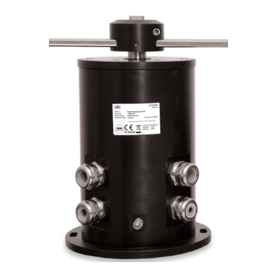
- Page 1 Rudder Feedback Unit MD/HD Installation and Operation Manual www.jrc.am...
-
Page 2: Table Of Contents
Contents I Preface......................4 I.1 Revision History................................ 4 I.2 Glossary..................................4 I.2.1 Definitions................................. 4 I.2.2 Abbreviations..............................5 I.3 Norms and Standards...............................6 II Warnings and Cautions................7 II.1 Warranty................................... 8 II.2 Storage..................................8 III Introduction....................9 1 Installation Instructions................10 1.1 Mechanical Installation............................10 1.1.1 Supplied Parts............................... - Page 3 4.4.1 Thales Certificate Rudder Feedback Unit MD....................30 4.4.2 Thales Certificate Rudder Feedback Unit HD....................31 5 Appendix B....................32 5.1 ISO 9001 Certificate Alphatron Marine R&D......................32 6 Appendix C....................33 6.1 EC Declaration of Conformity..........................33 3 | Contents...
-
Page 4: I Preface
I Preface The Rudder Feedback Unit is a high quality, ruggedized, easy to install rudder feedback unit. • Thoroughly read this instruction manual before installation and operation of the equipment. • We recommend to keep this manual nearby the equipment to ensure ready access to it. I.1 Revision History Revision No. -
Page 5: Abbreviations
Baud rate This is the transmission speed of serial interfaces in characters per second. Transmitting interval The frequency at which complete NMEA sentences are being transmitted in number of times per second. Factory setting Instrument setting for backlight color, language, number of connected apparatus, etc. as configured as a new instrument by the factory. -
Page 6: Norms And Standards
RFU MD Rudder Feedback Unit Medium Duty Rate Of Turn Volts Alternating Current Volts Direct Current Voyage Data Recorder Watt Table 2: Abbreviations I.3 Norms and Standards The complies with the applicable standards, norms and regulations: • IEC 60945 (2002) including IEC 60945 Corrigendum 1 (2008) •... -
Page 7: Warnings And Cautions
II Warnings and Cautions The signal words WARNING and CAUTION used in this manual indicate the degree of hazard that may be encountered by the user. These words are defined as: • WARNING • A WARNING indicates potential risk of injury or death to users of the product. •... -
Page 8: Ii.1 Warranty
• This product contains no operator serviceable parts. Service and repair shall only be carried out by personnel trained and certified by ALPHATRON MARINE. • CAUTION • Do not allow the instrument to fall or immerse into water. The equipment can be damaged. •... -
Page 9: Introduction
III Introduction The Rudder Feedback Unit can be used in a rudder angle indicator system and as a part of the control loop in a steering control system. There are two types of Rudder Feedback Units available: Rudder Feedback Unit MD and Rudder Feedback Unit HD. -
Page 10: Installation Instructions
1 Installation Instructions This chapter describes the installation of the Rudder Feedback Unit MD/HD. 1.1 Mechanical Installation • CAUTION • This product must be installed in accordance with the installation methods described in this manual. Acting otherwise will void the warranty. 1.1.1 Supplied Parts The Rudder Feedback Unit MD/HD is delivered as a fully assembled product. - Page 11 Figure 3: Example of a Foundation Cables Only screened cables should be used. The screen must be connected to the cable glands according to Figure 4: Using Cable Glands on page 11. Figure 4: Using Cable Glands Installing the Linkage Transmission The Linkage Transmission is delivered with all necessary parts except for the RFU LT TUBE.
- Page 12 Figure 5: Rudder Example with Linkage Transmission (Top View) Installing the Chain Transmission The Chain Transmission is delivered complete with a sprocket with 25 teeth (Rudder Feedback Unit side) and a sprocket with 28 teeth (rudder side), and parts to create the appropriate tension. When the Chain Transmission is used, the Rudder Feedback Unit can be placed in any direction compared to the rudder as long as it is easy accessible for installation and maintenance.
- Page 13 Figure 6: Rudder Example with Chain Transmission (Top View) The chain of the Chain Transmission is delivered with a total length of 2 meters, divided in a short and a long part. The short part has to be installed at the side of the Rudder Feedback Unit. The long part can be shortened by removing links to create the desired length.
-
Page 14: Module Electric Connections
Figure 8: Compression Spring After adjusting, nuts (11) and (12) must be secured, see Figure 7: Stud Bolt on page 13. 1.1.4 Module Electric Connections The Rudder Feedback Unit needs to be opened to connect the wires, see Opening Rudder Feedback Unit MD on page 14 and Opening Rudder Feedback Unit HD on page 16. - Page 15 INFO: Figure 10: Removing Rudder Feedback Unit MD Top 3. Disconnect the 2 connectors and the earth connection. The Rudder Feedback Unit MD is now open for connection of the wires according to Figure 19: Connection Diagram Rudder Feedback Unit MD on page 28. Figure 11: Rudder Feedback Unit MD Electric Connections When the connections have been made, replace the connectors and close the Rudder Feedback Unit MD.
-
Page 16: Opening Rudder Feedback Unit Hd
1.1.4.1.1 Adjusting Potentiometers Adjusting the Potentiometers The potentiometers are aligned in the factory. The middle position of the potentiometers corresponds with the mark on top of the axle and the red dot on top of the Rudder Feedback Unit MD. When further adjustment is to be made, this has to be done in the equipment connected to the Rudder Feedback Unit MD. - Page 17 Figure 13: Rudder Feedback Unit HD Electric Connections When the connections have been made, close the front hatch of the Rudder Feedback Unit HD. When replacing the screws, first apply the middle top and the middle bottom screw of the hatch and torque to 6,5 Nm. After this, all other screws can be replaced and torqued to 6,5 Nm.
-
Page 18: Cable
Figure 14: Rudder Feedback Unit HD Limit Switches Adjusting the Potentiometers The potentiometers are aligned in the factory. The middle position of the potentiometers corresponds with the mark on top of the axle and the red dot on top of the Rudder Feedback Unit HD. When further adjustment is to be made, this has to be done in the equipment connected to the Rudder Feedback Unit HD. -
Page 19: Operation
2 Operation I Operating the Rudder Feedback Unit The Rudder Feedback Unit can be used in a rudder angle indicator system and as a part of the control loop in a steering control system. The output can be connected to an Analog Interface Mk.2. There are two types of rudder feedback units available: Rudder Feedback Unit MD and Rudder Feedback Unit HD. - Page 20 zeroed. Moreover, without zeroing the axle the rudder readings can be completely wrong and so endanger ships operation and its personnel. The maximum angle that the axle (and the attached potentiometer) of the Rudder Feedback Unit can turn, is measured from the zero position marking.
-
Page 21: Maintenance
3 Maintenance • CAUTION • This product contains no operator serviceable parts. Service and repair shall only be carried out by personnel trained and certified by ALPHATRON MARINE. Maintenance and repair of the Rudder Feedback Unit should only be performed by personnel that is familiar with the Alphatron Rudder Feedback Unit. -
Page 22: Specifications
4 Appendix A Appendix A contains: 1. Specifications on page 22 2. Mechanical Drawings on page 23 3. Electric Diagrams on page 27 4. Thales Certificates on page 30 4.1 Specifications 4.1.1 Specifications Rudder Feedback Unit MD/HD Box Contents upon Delivery Environmental according to DNV 2.4 table 2.1 Rudder Feedback Unit MD 3109.0196... -
Page 23: Mechanical Drawings
4.2 Mechanical Drawings 4.2.1 Mechanical Drawing Rudder Feedback Unit MD Figure 15: Mechanical Drawing Rudder Feedback Unit MD 23 | Appendix A... -
Page 24: Mechanical Drawing Rudder Feedback Unit Hd
4.2.2 Mechanical Drawing Rudder Feedback Unit HD Figure 16: Mechanical Drawing Rudder Feedback Unit HD 24 | Appendix A... -
Page 25: Mechanical Drawing Rfu Linkage Transmission
4.2.3 Mechanical Drawing RFU Linkage Transmission Figure 17: Mechanical Drawing RFU Linkage Transmission 25 | Appendix A... -
Page 26: Mechanical Drawing Rfu Chain Transmission
4.2.4 Mechanical Drawing RFU Chain Transmission Figure 18: Mechanical Drawing RFU Chain Transmission 26 | Appendix A... -
Page 27: Electric Diagrams
4.3 Electric Diagrams The cable diagrams and connection diagrams illustrate the connections to hardware, power and other equipment. 27 | Appendix A... -
Page 28: Connection Diagram Rudder Feedback Unit Md
4.3.1 Connection Diagram Rudder Feedback Unit MD Figure 19: Connection Diagram Rudder Feedback Unit MD 28 | Appendix A... -
Page 29: Connection Diagram Rudder Feedback Unit Hd
4.3.2 Connection Diagram Rudder Feedback Unit HD Figure 20: Connection Diagram Rudder Feedback Unit HD 29 | Appendix A... -
Page 30: Thales Certificates
4.4 Thales Certificates 4.4.1 Thales Certificate Rudder Feedback Unit MD Figure 21: Thales Certificate Rudder Feedback Unit MD 30 | Appendix A... -
Page 31: Thales Certificate Rudder Feedback Unit Hd
4.4.2 Thales Certificate Rudder Feedback Unit HD Figure 22: Thales Certificate Rudder Feedback Unit HD 31 | Appendix A... -
Page 32: Iso 9001 Certificate Alphatron Marine R&D
5 Appendix B 5.1 ISO 9001 Certificate Alphatron Marine R&D Figure 23: ISO 9001 Certificate Alphatron Marine R&D 32 | Appendix B... -
Page 33: Ec Declaration Of Conformity
6 Appendix C 6.1 EC Declaration of Conformity Figure 24: EC Declaration of Conformity Rudder Feedback Unit MD/HD 33 | Appendix C... - Page 34 All over the world, close to the customer JRC/Alphatron Marine Schaardijk 23 (harbor 115) The information in this document is subject to change without notice and 3063 NH Rotterdam does not represent a commitment on the part of Alphatron Marine B.V.
Need help?
Do you have a question about the Alphatron Marine Rudder Feedback Unit HD and is the answer not in the manual?
Questions and answers