Table of Contents
Advertisement
Quick Links
NATURAL GAS MODELS:
PROPANE GAS MODELS:
SAFETY INFORMATION
WARNING
!
FIRE OR EXPLOSION HAZARD
Failure to follow safety warnings exactly
could result in serious injury, death, or
property damage.
- Do not store or use gasoline or other
fl ammable vapors and liquids in the vicinity of
this or any other appliance.
- WHAT TO DO IF YOU SMELL GAS:
•
Do not try to light any appliance.
•
Do not touch any electrical switch; do not
use any phone in your building.
•
Immediately call your gas supplier from a
neighbour's phone. Follow the gas
supplier's instructions.
•
If you cannot reach your gas supplier, call
the fi re department.
- Installation and service must be
performed by a qualifi ed installer, service
agency, or the supplier.
This appliance may be installed in an aftermarket,
permanently located, manufactured home (USA
only) or mobile home, where not prohibited by
local codes.
This appliance is only for use with the type of gas
indicated on the rating plate. This appliance is
not convertible for use with other gases, unless
a certifi ed kit is used.
INSTALLER:
Leave this manual with the appliance
CONSUMER:
Retain this manual for future reference
Wolf Steel Ltd., 24 Napoleon Rd., Barrie, ON, L4M 0G8 Canada / 103 Miller Drive, Crittenden, Kentucky, USA, 41030
$10.00
B30NTR-1 / B30NTRE-1
ADD PRODUCT CODE HERE (TRADE GOTHIC LT STD FONT)
B30PTR-1 / B30PTRE-1
Phone 1 (866) 820-8686 • www.napoleon.com • hearth@napoleon.com
INSTALLATION AND
ADD MANUAL TITLE
OPERATION MANUAL
CERTIFIED TO THE CANADIAN AND AMERICAN NATIONAL STANDARDS:
CSA 2.22 AND ANSI Z21.50 FOR VENTED DECORATIVE GAS APPLIANCES
IF INSTALLATION + OPERATION, ADD SERIAL
CSA /
INTERTEK
BARCODE LABEL ON THE OWNER'S MANUAL"
LOGO
Product Name / Code
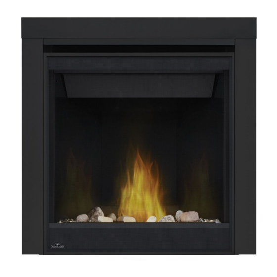
Ascent™ 30
(MUST use title from Price Book)
ADD ____ ILLUSTRATED
ADD PRODUCT IMAGE
FOR INDOOR USE ONLY
NUMBER LABEL HERE
IF SEPARATE MANUALS, ADD "PLACE
ENGLISH
FRENCH PG. 71
W415-2351 / B / 12.09.20
Advertisement
Table of Contents
Troubleshooting

Related Manuals for Napoleon Ascent 30


Summary of Contents for Napoleon Ascent 30
- Page 1 INTERTEK BARCODE LABEL ON THE OWNER’S MANUAL” LOGO Wolf Steel Ltd., 24 Napoleon Rd., Barrie, ON, L4M 0G8 Canada / 103 Miller Drive, Crittenden, Kentucky, USA, 41030 Phone 1 (866) 820-8686 • www.napoleon.com • hearth@napoleon.com $10.00 W415-2351 / B / 12.09.20...
- Page 2 safety information WARNING DANGER • This appliance is hot when operated and can cause severe burns if contacted. • Any changes or alterations to this appliance or its controls can be dangerous and is prohibited. HOT GLASS WILL CAUSE • Do not operate appliance before reading and BURNS.
- Page 3 • Do not allow wind or fans to blow directly into the appliance. Avoid any drafts that alter burner fl ame patterns. RAAK HET GLAS NIET AAN TOT HET IS AFGEKOELD. DUTCH safety information LAAT KINDEREN NOOIT HET GLAS AANRAKEN. WARNING Dit apparaat is voorzien van een barrière die is ontworpen om het risico van brandwonden door het hete kijkglas te beperken.
-
Page 4: Table Of Contents
table of contents general information electrical information rates and efficiencies battery back-up installation rating plate information optional wall switch mobile home installation gas installation dimensions operation (electronic) venting requirements pilot on demand typical vent installation operation (millivolt) special vent installations finish framing 2.2.1 periscope termination minimum framing dimensions... -
Page 5: General Information
standard checklist Installer: please fill out the following information Customer: Address: Date of Installation: Location of the appliance Installer: Dealer/Distributor contact number: Serial #: Model: Natural Gas: Propane: B30NTR-1 B30PTR-1 B30NTRE-1 B30PTRE-1 1.0 general information When the appliance is installed at elevations above 4,500ft (1372m), and in the absence of specific recommendations from the local authority having jurisdiction, the certified high altitude input rating shall be reduced at the rate of 4% for each additional 1,000ft (305m). - Page 6 general information WARNING • Always light the pilot whether for the first time or if the gas supply has run out, with the glass door opened or removed. • Provide adequate clearance for servicing and operating the appliance. • Provide adequate ventilation. •...
-
Page 7: Rating Plate Information
Recessed depth X” Profondeur d’encastré une face X” L’appareil doit être ventilé à l’aide de l’ensemble d’évacuation propre à Napoleon. Référez au *** Mantel X” from appliance opening *** Tablette X” de l’ouverture de l’appareil manuel d’installation pour les spécifications d’évacuation. Il est nécessaire de bien réinstaller et *** Maximum horizontal extension: *** L’extension horizontale maximale: X”. -
Page 8: Dimensions
general information dimensions W415-2351 / B / 12.09.20... -
Page 9: Venting Requirements
venting requirements 2.0 venting requirements WARNING • Risk of fi re. Maintain specifi ed air space clearances to vent pipe and appliance. • The vent system must be supported every 3’(0.9m) for both vertical and horizontal runs. Use support ring assembly W010- 0067 or equivalent non-combustible strapping to maintain the minimum clearance to combustibles for both vertical and horizontal runs. -
Page 10: Typical Vent Installation
The air terminal must remain unobstructed at all times. Examine the air terminal at least once a year to verify that it is unobstructed and undamaged. Rigid and fl exible venting systems must not be combined. Different venting manufacturer components must not venting requirements be combined. - Page 11 venting requirements 16" (40.6cm) minimum 40 ft (12m) Maximum 3 ft (1m) minimum 20" (50.8cm) Max. 24 3/16" (61.4cm) minimum plus rise * 24 3/16" (61.4cm) REAR VENT * See "venting" section W415-2351 / B / 12.09.20...
-
Page 12: Special Vent Installations
venting requirements special vent installations 2.2.1 periscope termination Use the periscope kit to locate the air termination above grade. The periscope must be installed so that when fi nal grading is completed, the bottom air slot is located a minimum 12” (305mm) above grade. The maximum allowable vent length (including both rise and run) is 10’... -
Page 13: Minimum Air Terminal Location
venting requirements minimum air terminal location clearances Covered balcony applications ††* = 3 feet ≤ 15 feet = 2 x ACTUAL (0.9m) (4.6m) note: INSTALLATIONS Wall terminals are for illustration purposes only. Size and shapes may vary. CANADA U.S.A. 12” (30.5cm) 12”... -
Page 14: Venting Application Flow Chart
venting requirements venting application flow chart TOP EXIT Horizontal Termination Vertical Termination Vertical rise is equal Vertical rise is equal Vertical rise is less Vertical rise is less to or greater than to or greater than than horizontal run than horizontal run the horizontal run the horizontal run Horizontal run +... -
Page 15: Elbow Vent Length Values
venting requirements elbow vent length values FEET INCHES MILLIMETERS 1° 0.03 12.7 15° 0.45 152.4 30° 11.0 279.4 45° 1.35 16.0 406.4 90°* 32.0 812.8 * The fi rst 90° offset has a zero value and is shown in the formula as - 90° top exit horizontal termination 15.1A ) <... - Page 16 venting requirements ) > (V Simple venting configuration See graph to determine the required vertical rise V for the required horizontal run H (only one 90° elbow) 150 (381) 147 (373) REQUIRED VERTICAL 100 (254) RISE IN INCHES (CENTIMETERS) V 57 (145) 50 (127) 8 (20.3)
-
Page 17: Rear Exit Horizontal Termination
venting requirements rear exit horizontal termination ) < (V Simple venting configuration See graph to determine the required vertical rise V for the required (only two 90° elbows) horizontal run H 40 (12.2) 38.3 (11.7) REQUIRED 30 (9.1) VERTICAL RISE IN 20 (6.1) FEET (METERS) V... - Page 18 venting requirements ) > (V Simple venting configuration See graph to determine the required vertical rise V for the (only two 90° elbows) required horizontal run H 12.5 (3.8) 12.25 (3.7) REQUIRED VERTICAL RISE IN 8.3 (2.54) FEET (METERS)V (1.68) 4.2 (1.3) (0.3) 12.5...
-
Page 19: Top And Rear Exit Vertical Termination
venting requirements top and rear exit vertical termination ) < (V See graph to determine the required vertical rise V for the Simple venting configurations. required horizontal run H 40 (12.2) 30 (9.1) REQUIRED VERTICAL RISE IN FEET 20 (6.1) (METERS)V 10 (3.1) 3 (0.9) - Page 20 venting requirements ) > (V See graph to determine the required vertical rise V for the Simple venting configurations. required horizontal run H 20 (6.1) 19 (5.8) REQUIRED VERTICAL 10 (3.1) RISE IN FEET 3 (0.9) (METERS)V (1.5) (3.1) (4.6) (6.1) (7.6) (9.1)
-
Page 21: Rear Exit
venting requirements 2.10 rear exit WARNING • Failure to create a seal to the firebox with the exhaust collar assembly will cause the appliance to function improperly and can cause injury or property damage. Fig. 1 Remove the safety barrier and glass front, refer to "safety barrier &... -
Page 22: Top Exit
venting requirements 2.12 top exit WARNING • Failure to install the cover plate and gasket will cause the appliance to function improperly and can cause injury or property damage. This appliance is factory shipped as a rear vent model equipped with a #50 burner orifice. This orifice size is suitable for rear vent installations with 0"... - Page 23 3.0 rough framing rough framing note: When using optional fi nishing accessories, the framing dimensions and fi nishing materials may differ from what is outlined in the section below; refer to the leafl et instructions supplied in the accessory kit for specifi c framing and fi nishing specifi cations.
-
Page 24: Rough Framing
rough framing minimum framing dimensions 29 1/2” SIDE WALL (75cm) 2” (51mm) 30 1/2” (77.5cm) Do not put objects in front of the appliance (minimum distance of 4 feet) 14 1/2” (36.8cm) * HORIZONTAL VENT SECTIONS: A minimum of 1" (25mm) at the bottom and sides and 3" (76mm) at the top of the vent pipe on all horizontal runs to combustibles is required. -
Page 25: Minimum Enclosure Clearances
rough framing minimum enclosure clearances TOP VENT TOP EXIT ENCLOSURE The appliance requires a minimum non-combustible enclosure height of 50 1/2" (1283mm). For temperature requirements, the enclosure space around and above the appliance must be left unobstructed. NOTE: The vent shield is telescopic and must be adjusted to shield the full depth of combustible wall penetration. - Page 26 rough framing REAR VENT For rear vent termination not exceeding 10" (254mm) of horizontal vent run. REAR EXIT ENCLOSURE The appliance requires a minimum enclosure height of 41 5/8" (1057mm). For temperature requirements, the enclosure space around and above the appliance must be left unobstructed. NOTE: The vent shield is telescopic and must be adjusted to shield the full depth of combustible wall penetration.
- Page 27 rough framing MAXIMUM REAR VENT CLEARANCES (EXAMPLE 1) 24 3/16" (61.4cm) REAR EXIT ENCLOSURE The appliance requires a minimum enclosure height of 41 5/8" (1057mm). For temperature requirements, the enclosure space around and above the appliance must be left unobstructed. NOTE: The vent shield is telescopic and must be adjusted to shield the full depth of combustible wall penetration.
- Page 28 rough framing MAXIMUM REAR VENT CLEARANCES (EXAMPLE 2) 24 3/16" (61.4cm) REAR EXIT ENCLOSURE The appliance requires a minimum enclosure height of 41 5/8" (1057mm). For temperature requirements, the enclosure space around and above the appliance must be left unobstructed. NOTE: The vent shield is telescopic and must be adjusted to shield the full depth of combustible wall penetration.
- Page 29 rough framing note: For heavier finishing materials such as marble, we recommend adding extra support to the frame. Ensure there is adequate floor support for the appliance and finishing material. Before framing your appliance, determine vent requirements before deciding the final location of the appliance. After rough framing, place the appliance in its final position.
- Page 30 4.0 venting installation venting installation WARNING • Ensure to unpack all loose materials from inside the fi rebox prior to connecting the gas and electrical supply • If your appliance is supplied with a remote, ensure the remote receiver is in the “OFF” position prior to connecting the gas and electrical supply to the appliance.
-
Page 31: Venting Installation
venting installation horizontal installation WARNING • The fi restop assembly must be installed with the vent shield to the top. • Terminals must not be recessed into a wall or siding more than the depth of the return fl ange of the mounting plate. -
Page 32: Vertical Installation
venting installation vertical installation This application occurs when venting through a roof. Installation kits for various roof pitches are available from your authorized dealer / distributor. See the “accessories” section to order specifi c kits required. A. Determine the air terminal location, cut and frame a square opening, as illustrated, in the ceiling and the roof to provide the minimum 1"... -
Page 33: Using Either Flexible Or Rigid Vent
venting installation using either flexible or rigid vent components WARNING • Do not allow the inner fl ex pipe to bunch up on horizontal or vertical runs and elbows. Keep it pulled tight. • Spacers are attached to the inner fl ex pipe at predetermined intervals to maintain an even air gap to the outer fl ex pipe. -
Page 34: Vertical Air Terminal Installation
venting installation 4.3.2 vertical air terminal installation WARNING • Maintain a minimum 2” (51mm) space between the air inlet base and the storm collar. note: Fastening hardware provided with appropriate roof terminal and liner kits. Fasten the roof support to the roof using 6 screws. The roof support is optional. -
Page 35: Horizontal Air Terminal Installation
venting installation 4.3.4 horizontal air terminal installation Move the appliance into position. Measure #10x2" the vent length required between terminal and SCREWS appliance taking into account the additional CAULKING length needed for the fi nished wall surface and any 2” (50.8mm) overlaps between venting INNER components. -
Page 36: Vertical Air Terminal Installation
venting installation 4.3.5 vertical air terminal installation WARNING • Maintain a minimum 2” (51mm) space between the air inlet base and the storm collar. note: Fastening hardware provided with appropriate roof terminal and liner kits. Before attaching elbows to the collars on the back of the appliance, 1 1/2” (38.1mm) will need to be trimmed off the 4”... -
Page 37: Vertical Through Existing Chimney
venting installation vertical through existing chimney WARNING • Risk of fi re. • Co-axial to co-linear venting confi gurations must only be used in a non-combustible chimney or enclosure. Installation in a combustible enclosure could result in a fi re. This appliance is designed to be attached to a 3”... -
Page 38: Restricting Vertical Vents
venting installation 4.4.1 restricting vertical vents WARNING • Turn off gas and electrical supply before servicing the appliance. • Appliance may be hot, do not service until appliance is cool. • For safe and proper operation of the appliance, follow the venting instruction exactly. •... -
Page 39: Electrical Information
5.0 electrical information electrical information WARNING • Do not wire 110 volts to the valve or wall switch. (where applicable) GREEN ON / OFF ORANGE SWITCH TRANSFORMER IPI / CPI ON / OFF BATTERY HOUSING ELECTRONIC DISCONNECT THESE VALVE CONNECTIONS TO THE ON/OFF SWITCH. -
Page 40: Battery Back-Up Installation
electrical information battery back-up installation note: In the event of a power failure, your appliance can be operated using the battery back-up supplied. Remove the safety barrier by lifting it up and off of the four shoulder screws. Locate your battery holder, this would have been supplied in the manual baggie. Locate the red and black wires from the control module to connect to the battery holder, as shown below. -
Page 41: Optional Wall Switch
electrical information optional wall switch WARNING • Do not connect either the wall switch, thermostat or gas valve directly to 110 volt electricity. For ease of accessibility, an optional remote wall switch or millivolt thermostat may be installed in a convenient location. -
Page 42: Operation (Electronic)
7.0 operation (electronic) electrical information WARNING • If you do not follow these instructions exactly, a fi re or explosion may result causing property damage, personal injury, or loss of life. • If applicable, always light the pilot whether for the fi rst time or if the gas supply has run out with the glass door opened or removed. -
Page 43: Pilot On Demand
In order to start your pilot, turning the main burner on with the switch, remote or thermostat and then turning it off will reactivate the continuous pilot mode and reset the seven day timer. For further information, refer to www.napoleon.com/pilotondemand. 31.2A... -
Page 44: Operation (Millivolt)
8.0 operation (millivolt) operation WARNING • If you do not follow these instructions exactly, a fi re or explosion may result causing property damage, personal injury, or loss of life. • If applicable, always light the pilot whether for the fi rst time or if the gas supply has run out with the glass door opened or removed. -
Page 45: Finish Framing
9.0 finish framing finish framing minimum framing dimensions 35" 889mm 14 1/2" 368mm W415-2351 / B / 12.09.20... -
Page 46: Finishing
10.0 finishing finishing WARNING • Risk of fire! • Never obstruct the front opening of the appliance. • The front of the appliance must be finished with any non-combustible materials such as brick, marble, granite, etc., provided that these materials do not go below the specified dimension, as illustrated. •... -
Page 47: Front Hood Installation
finishing 10.2 front hood installation note: This hood must be installed, if it has not already been factory installed. Safety door and screen must be removed. Remove the securing screws from the top of the firebox, as shown. Install the front hood, ensure it is angled downward when installed. Reinstall the previously removed securing screws. -
Page 48: Non-Combustible Facing Material
finishing 10.3 non-combustible facing material WARNING Non-combustible facing material must not project more than 4” (101.6mm) from the face of the door (all four sides). If greater projections are desired, increase the clearance to the sides, bottom and top by 2” (50.8mm) for every additional 1”... -
Page 49: Minimum Mantel Clearances
finishing 10.4 minimum mantel clearances WARNING • Risk of fi re. Maintain all specifi ed air space clearances to combustibles. Failure to comply with these instructions may cause a fi re or cause the appliance to overheat. Ensure all clearances (i.e. back, side, top, vent, mantel, front, etc.) are clearly maintained. -
Page 50: Recessed Installation
finishing 10.5 recessed installation WARNING • Installing a television or other electronics above the appliance may cause discolouration, melting, or damage to the electronics. Use clearances as guidelines and refer to your TV manufacturer’s instructions for further information Image Before placing anything above a heat source, it is advisable to follow proper clearances and manufacturer’s instructions. -
Page 51: Log Placement
• The logs are fragile and should be handled with care. logs exclusive to Napoleon, provide a unique and realistic glowing effect that is different in every PHAZER 48.1 installation. Log colours may vary. During the initial use of the appliance, the colours will become more uniform as colour pigments burn in during the heat activated curing process. -
Page 52: Logo Placement
finishing Reinstall the door and safety screen. Place the right crossover log (W135-0579) onto the two remaining pins. 10.7 logo placement 1/2"(12.7mm) INSERT Remove the backing of the logo supplied and place, as illustrated. LOGO IMAGE 1/2"(12.7mm) HERE 45.5 W415-2351 / B / 12.09.20... -
Page 53: Adjustments
11.0 adjustments adjustments 11.1 pilot burner adjustment Adjust the pilot screw to provide properly sized PILOT ELECTRODE flame. Turn in a clockwise direction to reduce the BURNER ELECTRONIC Adjust the pilot screw to provide properly sized fl ame. Turn in a clockwise direction to reduce the gas fl ow. 3/8”... -
Page 54: Flame Characteristics
adjustments SIT MILLIVOLT 11.3 flame characteristics 3/8” - 1/2” (9.5mm - 12.7mm) It’s important to periodically perform a visual check of the pilot and burner flames. Compare them to the ADD IMAGE Flame must envelop illustration provided. If any flames appear abnormal, upper call a service person. -
Page 55: Maintenance
maintenance 12.0 maintenance WARNING • Turn off the gas and electrical power before servicing the appliance. • Appliance may be hot. Do not service until appliance has cooled. • Do not use abrasive cleaners on glass. • Do not paint the pilot assembly. This appliance and its venting system should be inspected before use and at least annually by a qualifi ed service person. -
Page 56: Annual Maintenance
maintenance 12.1 annual maintenance WARNING • Annual maintenance should be performed by a qualifi ed service technician • The fi rebox becomes very hot during operation. Let the appliance cool completely or wear heat resistant gloves before conducting service. • Never vacuum hot embers. -
Page 57: Door Glass Replacement
maintenance 12.2 door glass replacement WARNING • Do not use substitute materials. • Glass may be hot. Do not touch glass until cooled. • Care must be taken when removing and disposing of any broken door glass or damaged components. Be sure to vacuum up any broken glass from inside appliance before operation. -
Page 58: Replacement Parts
13.0 replacement parts replacement parts WARNING • Failure to position the parts in accordance with this manual or failure to use only parts specifi cally approved with this appliance may result in property damage or personal injury. Contact your dealer for questions concerning prices and policies on replacement parts. Normally, all parts can be ordered through your Authorized dealer / distributor. -
Page 59: Overview
replacement parts W415-2351 / B / 12.09.20... -
Page 60: Electronic Valve Train Assembly
replacement parts W415-2351 / B / 12.09.20... -
Page 61: Millivolt Valve Train Assembly
replacement parts W415-2351 / B / 12.09.20... -
Page 62: Accessories
14.0 accessories accessories W415-2351 / B / 12.09.20... -
Page 63: Troubleshooting (Electronic)
15.0 troubleshooting (electronic) troubleshooting (electronic) WARNING • Always light the pilot whether for the fi rst time or if the gas supply has run out, with the glass door open or removed. • Turn off gas and electrical power before servicing the appliance. •... - Page 64 Check that venting is installed correctly. appliances). Room is in negative pressure; increase fresh air supply. troubleshooting (electronic) symptom problem test solution Pilot will not light. Makes Wiring: short, loose, or damaged Verify the thermocouple/sensor is clean and the wiring is undamaged. Verify the interrupter block is not damaged or too tight.
- Page 65 Wire connector pins are bent. Straighten pins. Valve wiring is damaged. Replace valve. troubleshooting (electronic) symptom problem test solution Lights or blower Control module switch in Verify ON/OFF switch is in the “I” position which denotes on. won’t function (if wrong position.
-
Page 66: Troubleshooting (Millivolt)
16.0 troubleshooting (millivolt) troubleshooting (millivolt) WARNING • Always light the pilot whether for the fi rst time or if the gas supply has run out, with the glass door open or removed. • Turn off gas and electrical power before servicing the appliance. •... - Page 67 troubleshooting (millivolt) symptom problem test solution Pilot will not light. No spark at pilot burner. Check if pilot can be lit by a match. Check that the wire is connected to the push button ignitor. EI PILOT MV PILOT ODS PILOT Check if the push button ignitor needs tightening.
-
Page 68: Warranty
Napoleon neither assumes, nor authorizes any third party to assume, on its behalf, any other liabilities with respect to the sale of this product. Napoleon will not be responsible for: over- fi ring, downdrafts, spillage caused by environmental conditions such as rooftops, buildings, nearby trees, hills, mountains, inadequate vents or ventilation, excessive venting confi gurations, insuffi cient makeup air, or negative air pressures which may or may not be caused by mechanical systems such as exhaust fans, furnaces, clothes dryers, etc. - Page 69 notes 29.1 W415-2351 / B / 12.09.20...
- Page 70 NAPOLEON CELEBRATING OVER 40 YEARS OF HOME COMFORT PRODUCTS 7200, Route Transcanadienne, Montréal, Québec H4T 1A3 24 Napoleon Road, Barrie, Ontario, Canada L4M 0G8 214 Bayview Drive, Barrie, Ontario, Canada L4N 4Y8 103 Miller Drive, Crittenden, Kentucky, USA 41030 De Riemsdijk 22, 4004 LC Tiel, The Netherlands Phone: 1-866-820-8686 napoleon.com...
Need help?
Do you have a question about the Ascent 30 and is the answer not in the manual?
Questions and answers