Table of Contents
Advertisement
NOTE: Read the entire instruction manual before starting the
installation.
TABLE OF CONTENTS
SAFETY CONSIDERATIONS .....................................................1
INTRODUCTION ..........................................................................2
RECEIVING AND INSTALLATION ..........................................2
ICM FIOP PRE-START-UP..........................................................2
Electrical Connections ..............................................................2
Control Voltage Connections ..............................................2
Standard Connection............................................................2
Easy Select™-583B ..........................................................2
583B Sequence of Operation ..............................................4
Easy Select™-683B ..........................................................5
683B Sequence of Operation ..............................................7
Easy Select™-702B & 602B............................................7
702B & 602B Sequence Of Operation...............................9
ICM FIOP START-UP ................................................................10
583B Start-Up (ICM FIOP)....................................................10
683B Start-Up (ICM FIOP)....................................................10
702B: Start-Up (ICM FIOP) ..................................................11
602B: Start-Up (ICM FIOP) ..................................................11
ELECTRICAL DATA & SCHEMATICS-ICM FIOP.............12
Physical Data & Electrical Schematics..................................12
Tables For System Set-Up......................................................12
CARE AND MAINTENANCE...................................................12
TROUBLESHOOTING ...............................................................13
START-UP CHECKLIST............................................................13
NOTE TO INSTALLER - READ THESE INSTRUCTIONS
CAREFULLY AND COMPLETELY before installing this unit.
Also, make sure the Owner's Manual and Service Instructions are
left with the unit after installation.
SAFETY CONSIDERATIONS
Installation and servicing of air-conditioning equipment can be
hazardous due to system pressure and electrical components. Only
trained and qualified personnel should install, repair, or service
air-conditioning equipment.
Untrained personnel can perform basic maintenance functions of
cleaning coils and filters. All other operations should be performed
by trained service personnel. When working on air-conditioning
equipment, observe precautions in the literature, tags, and labels
attached to the unit, and other safety precautions that may apply.
Follow all safety codes. Wear safety glasses and work gloves. Use
quenching cloth for unbrazing operations. Have fire extinguisher
available for all brazing operations.
installation, start-up,
and operating instructions
ICM FIOP INSTALLATION INSTRUCTIONS
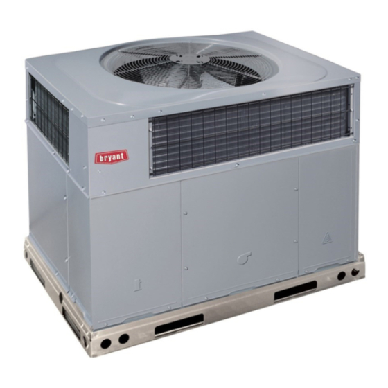
Fig. 1-Puron® Unit (583B Shown)
WARNING: Improper installation, adjustment, alter-
ation, service, maintenance, or use can cause explosion,
fire, electric shock, or other occurrences, which could
cause serious injury or death or damage your property.
Consult a qualified installer or service agency for infor-
mation or assistance. The qualified installer or agency
must use only factory-authorized kits or accessories when
modifying this product.
Recognize safety information. This is the safety-alert symbol
When you see this symbol on the product or in instructions or
manuals, be alert to the potential for personal injury.
Understand the signal words - DANGER, WARNING, CAU-
TION, and NOTE. Danger identifies the most serious hazards,
which will result in severe personal injury or death. Warning
indicates a condition that could cause serious personal injury or
death. Caution is used to identify unsafe practices, which would
result in minor personal injury or product and property damage.
NOTE is used to highlight suggestions which will result in
enhanced installation, reliability, or operation.
The power supply (volts, phase, and hertz) must correspond to that
specified on unit rating plate.
The electrical supply provided by the utility must be sufficient to
handle load imposed by this unit. Electrical supply must match the
voltage requirements listed on unit rating plate.
This installation must conform with local building codes and with
NEC (National Electrical Code). Refer to provincial and local
plumbing or waste water codes and other applicable local codes.
Approved for outdoor installation on wood flooring or on class A,
B or C roof covering materials.
-1-
Cancels: II 583B-24-2
583B
683B
602B
702B
II 583B-24-3
11-01
C99087
.
Advertisement
Table of Contents

Related Manuals for Bryant 702B


Summary of Contents for Bryant 702B
-
Page 1: Table Of Contents
583B Sequence of Operation ...4 Easy Select™—683B ...5 683B Sequence of Operation ...7 Easy Select™—702B & 602B...7 702B & 602B Sequence Of Operation...9 ICM FIOP START-UP ...10 583B Start-Up (ICM FIOP)...10 683B Start-Up (ICM FIOP)...10 702B: Start-Up (ICM FIOP) ...11 602B: Start-Up (ICM FIOP) ...11... -
Page 2: Introduction
Motor Master™ II low ambient kit is required. These instructions cover the installation of a Bryant Small Pack- aged Product with ICM motor-factory installed option (FIOP). This option can be selected as a FIOP on gas heating/electric cooling (583B), dual fuel–electric heat pump with gas heat... - Page 3 POWER LEADS RED(R) (SEE UNIT BRN(C) WIRING LABEL) WHI(W1) GRA(W2) SPLICE BOX LEGEND Field Control-Voltage Wiring Field High-Voltage Wiring Fig. 4—702B High- and Control-Voltage Connections HIGH VOLTAGE POWER LEADS (SEE UNIT WIRING LABEL) FIELD-SUPPLIED FUSED DISCONNECT CONTROL BOX BLK(DH) YEL(Y)
-
Page 4: 583B Sequence Of Operation
(3.) SYSTEM TYPE-Factory selected on 583B system AC- AIR CONDITIONER. (4.) AC/HP CFM ADJUST-Select HIGH for 042 & 048, NOM for 036 & 060, and LO for 024 & 030.. (5.) ON/OFF DELAY-Factory selected 0/90 profile. (6.) CONTINUOUS FAN-Select desired fan speed when ther- mostat is set to continuous fan. -
Page 5: Easy Select™-683B
“On” delay and a 45 sec. “Off” delay. E. Easy Select™—683B NOTE: Either the Bryant Thermidistat™ or Dual Fuel ther- mostat is required for operation of the dual-fuel (683B) units. Be sure to follow the installation instructions supplied with the Thermidistat™. - Page 6 (4.) ENH (enhanced) selection provides a 30 sec. cooling & heat pump on delay with no airflow, plus 150 seconds at 70 percent airflow and no off delay for added comfort. This will minimize cold blow in heat pump operation and could enhance system efficiency.
-
Page 7: 683B Sequence Of Operation
HEATER/MOTOR 12 PIN CONNECTOR Fig. 11—Detail of SPP Printed-Circuit Board EASY SELECT™ CONFIGURATION TAPS FOR 702B & 602B Easy Select™ taps are used by the installer to configure a system. The ICM motor uses the selected taps to modify its operation to a pre-programmed table of airflows. - Page 8 (2.) AC/HP SIZE-Factory selected to match system size in- stalled, please verify. (3.) SYSTEM TYPE-Factory selected AC (702B) or HP-EFF (602B). (4.) AC/HP CFM ADJUST-Select HIGH for 042 & 048, NOM for 036 & 060, and LO for 024 & 030.
-
Page 9: 702B & 602B Sequence Of Operation
ACCESSORY INSTALLATION a. ACCESSORY ELECTRIC HEATERS Electric heaters may be installed with the 702B & 602B units per instructions supplied with electric heater package. See unit rating plate for factory-approved electric heater kits. b. AUXILIARY TERMINALS The AUX and HUM terminals on the Easy Select™... -
Page 10: Icm Fiop Start-Up
value. If circuit R to G is open (0–v.) for super dehumidify mode, the motor delivers reduced airflow to maximize the humidity removal of the system while minimizing over cooling. e. ELECTRIC HEATING MODE (1.) Thermostat closes circuit R to W/W1, or W2—The unit delivers the selected electric heat airflow. -
Page 11: 702B: Start-Up (Icm Fiop)
Refer to Indoor Airflow and Airflow Tables on the following pages to adjust heating airflow when required. III. 702B: START-UP (ICM FIOP) CHECKING COOLING CONTROL OPERATION–Start and check the unit for proper cooling control operation as follows: (1.) Place room thermostat SYSTEM switch in OFF position. -
Page 12: Electrical Data & Schematics-Icm Fiop
ELECTRICAL DATA & SCHEMATICS—ICM FIOP I. PHYSICAL DATA & ELECTRICAL SCHEMATICS Use the Physical Data and Electrical Tables on the following pages for information that applies to Bryant Puron® units with the ICM indoor motor FIOP. AIRFLOW & TEMPERATURE RISE TABLES—ICM FIOP II. -
Page 13: Troubleshooting
TABLE 2—ICM FIOP PHYSICAL DATA—UNIT 583B (CONTINUED) THIS DATA APPLIES TO 583B UNITS WITH THE ICM INDOOR MOTOR FIOP UNIT SIZE 583B NOMINAL CAPACITY (ton) OPERATING WEIGHT (lb.) COMPRESSORS Quantity REFRIGERANT (R-410A) Quantity (lb.) REFRIGERANT METERING DEVICE Orifice ID (in.) Check-Flo-Rater™... - Page 14 C01035 Fig. 14—ICM FIOP Electric Schematic—Unit 583B —14—...
- Page 15 THIS DATA APPLIES TO 683B UNITS WITH THE ICM INDOOR MOTOR FIOP UNIT SIZE 683B NOMINAL CAPACITY (ton) OPERATING WEIGHT (lb.) COMPRESSORS Quantity REFRIGERANT (R-410A) Quantity (lb.) REFRIGERANT METERING DEVICE Orifice Indoor (in.) Check-Flo-Rater™ Piston REFRIGERANT METERING DEVICE Orifice Outdoor (in.) Check-Flo-Rater™...
- Page 16 TABLE 5—ICM FIOP PHYSICAL DATA—UNIT 683B (CONTINUED) THIS DATA APPLIES TO 683B UNITS WITH THE ICM INDOOR MOTOR FIOP UNIT SIZE 683B NOMINAL CAPACITY (ton) OPERATING WEIGHT (lb.) COMPRESSORS Quantity REFRIGERANT (R-410A) Quantity (lb.) REFRIGERANT METERING DEVICE Orifice Indoor (in.) Check-Flo-Rater™...
- Page 17 C01101 Fig. 15—ICM FIOP Electric Schematic—Unit 683B —17—...
- Page 18 TABLE 7—ICM FIOP PHYSICAL DATA—UNIT 702B THIS DATA APPLIES TO 702B UNITS WITH THE ICM INDOOR MOTOR FIOP UNIT SIZE NOMINAL CAPACITY (ton) OPERATING WEIGHT (lb) COMPRESSOR REFRIGERANT (R-410A) Quantity (lb) REFRIGERANT METERING DEVICE Orifice ID (in.) CONDENSER COIL Rows...Fins/in.
- Page 19 TABLE 8—702B WITH ICM FIOP ELECTRICAL DATA VOLTAGE COMPRESSOR RANGE UNIT V-PH-HZ SIZE 702B MIN MAX 208/230–1–60 187 13.5 208/230–1–60 187 14.7 208/230–1–60 187 15.4 208/230–1–60 187 18.6 208/230–1–60 187 20.5 208/230–1–60 187 27.6 * Heater capacity (kW) based on heater voltage of 208-v & 240-v. If power distribution voltage to unit varies from rated heater voltage, heater kW will vary accordingly. Refer to Multiplication Factors Table 23.
- Page 20 C01037 Fig. 16—ICM FIOP Electrical Schematic—702B —20—...
- Page 21 TABLE 9—ICM FIOP PHYSICAL DATA—UNIT 602B THIS DATA APPLIES TO 602B UNITS WITH THE ICM INDOOR MOTOR FIOP UNIT SIZE NOMINAL CAPACITY (ton) OPERATING WEIGHT (lb.) COMPRESSOR QUANTITY TYPE REFRIGERANT REFRIGERANT METERING DEVICE Refrigerant (R-410A) Quantity (lb.) ORIFICE ID (in.) ORIFICE OD (in.) OUTDOOR COIL Rows...
- Page 22 TABLE 10—602B WITH ICM FIOP ELECTRICAL DATA VOLTAGE COMPRESSOR RANGE UNIT V-PH-HZ SIZE 602B MIN MAX 208/230–1–60 187 208/230–1–60 187 208/230–1–60 187 208/230–1–60 187 208/230–1–60 187 208/230–1–60 187 * Heater capacity (kW) based on heater voltage of 208-v & 240-v. If power distribution voltage to unit varies from rated heater voltage, heater kW will vary accordingly. Refer to Multiplication Factors Table 23.
- Page 23 c01036 Fig. 17—ICM FIOP Electrical Schematic—602B —23—...
- Page 24 TABLE 11–583B & 683B COOLING (AND HEAT PUMP HEATING-683B ONLY) CFM ADJUST PIN SELECT UNIT SIZE EXTERNAL STATIC 0.0–0.4 PRESSURE RANGE COOLING † COOLING DEHUMIDIFY HEAT PUMP COMFORT (683B Only) COOLING † COOLING DEHUMIDIFY HEAT PUMP COMFORT (683B Only) COOLING † 1025 COOLING DEHUMIDIFY...
- Page 25 TABLE 15—583B & 683B ICM AIR FLOW VS. TEMPERATURE RISE CHART RATED GAS COOLING UNIT INPUT RATE SIZE (X 1000) (583B Only) 583B & 683B TABLE 16—702B/602B COOLING & HEATING DRY COIL ICM AIRFLOW CFM ADJUST PIN SELECT UNIT SIZE EXTERNAL STATIC 0.0–0.4 PRESSURE RANGE COOLING † COOLING DEHUMIDIFY...
- Page 26 TABLE 17—702B/602B COOLING & HEATING DRY COIL ICM AIRFLOW CFM ADJUST PIN SELECT UNIT SIZE EXTERNAL STATIC PRESSURE RANGE COOLING † COOLING DEHUMIDIFY HEAT PUMP COMFORT (602B Only) COOLING † COOLING DEHUMIDIFY HEAT PUMP COMFORT (602B Only) COOLING † COOLING...
- Page 27 TABLE 21—ICM FIOP WET COIL PRESSURE DROP (IN. WG) UNIT SIZE 0.005 0.007 0.010 0.012 – 0.007 0.010 0.012 – – – 0.019 – – – – – – – – – – – – TABLE 22—FILTER PRESSURE DROP TABLE (IN. WG) FILTER SIZE 20 X 20 X 1 0.05 0.07 0.08 0.10 0.12...
- Page 28 QUICK REFERENCE GUIDE SET-UP INSTRUCTIONS FOR WARMER HEATING TEMPERATURES AND SUPER HUMIDITY CONTROL IN COOLING 9 PIN CONNECTOR ICM PRINTED CIRCUIT BOARD SEC1 SEC2 EASY SELECT AUX HEAT KW/CFM 0-30 0-20 0-10 1075 AC/HP SIZE SYSTEM TYPE HP-COMFORT HP-EFF AC/HP CFM ADJUST ON/OFF DELAY CONTINUOUS FAN HEATER/MOTOR...
-
Page 29: Start-Up Checklist
START-UP CHECKLIST (Remove and Store in Job File) I. Preliminary Information MODEL NO.:_________________________________ SERIAL NO.:__________________________________ DATE:_______________________________________ TECHNICIAN:_________________________________ II. PRE-START-UP (Insert checkmark in box as each item is completed) ( ) VERIFY THAT ALL PACKING MATERIALS HAVE BEEN REMOVED FROM UNIT ( ) REMOVE ALL SHIPPING HOLD DOWN BOLTS AND BRACKETS PER INSTALLATION INSTRUCTIONS ( ) CHECK ALL ELECTRICAL CONNECTIONS AND TERMINALS FOR TIGHTNESS ( ) CHECK GAS PIPING FOR LEAKS (WHERE APPLICABLE) - Page 30 © 2001 Bryant Heating & Cooling Systems 7310 W. Morris St. Indianapolis, IN 46231 —30— Printed in U.S.A. ii583b243 Catalog No. 5358-308...
Need help?
Do you have a question about the 702B and is the answer not in the manual?
Questions and answers