Advertisement
Quick Links
707C--C, 707C--F
Legacy™14 SEER Single-Packaged Air
Conditioner System with Puron®
(R-410A) Refrigerant
Single Phase 2-5 Nominal Tons (Sizes 24-60)
Three Phase 3-5 Nominal Tons (Sizes 36-60)
IMPORTANT: Effective January 1, 2015, all split system and packaged
air conditioners must be installed pursuant to applicable regional
efficiency standards issued by the Department of Energy.
NOTE: Read the entire instruction manual before starting the
installation.
NOTE:
Installer: Make sure the Owner's Manual and Service
Instructions are left with the unit after installation.
Table of Contents
Safety Considerations . . . . . . . . . . . . . . . . . . . . . . . . . . . . . . . . . . . . . . . 1
Introduction. . . . . . . . . . . . . . . . . . . . . . . . . . . . . . . . . . . . . . . . . . . . . . . 2
Receiving and Installation . . . . . . . . . . . . . . . . . . . . . . . . . . . . . . . . . . . 2
Pre-Start-up . . . . . . . . . . . . . . . . . . . . . . . . . . . . . . . . . . . . . . . . . . . . . . 11
Start-up . . . . . . . . . . . . . . . . . . . . . . . . . . . . . . . . . . . . . . . . . . . . . . . . . 11
Maintenance . . . . . . . . . . . . . . . . . . . . . . . . . . . . . . . . . . . . . . . . . . . . . 28
Troubleshooting . . . . . . . . . . . . . . . . . . . . . . . . . . . . . . . . . . . . . . . . . . 31
Start-up Checklist . . . . . . . . . . . . . . . . . . . . . . . . . . . . . . . . . . . . . . . . . 31
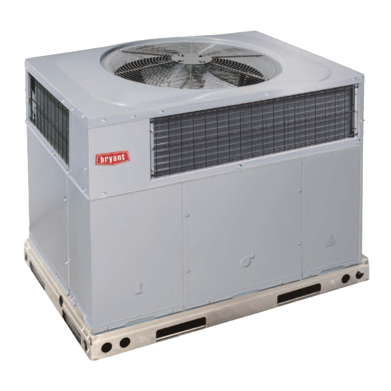
Fig. 1 - Unit 707C
Safety Considerations
Improper installation adjustment, alteration, service, maintenance, or use
can cause explosion, fire, electrical shock, or other conditions which
may cause death, personal injury, or property damage. Consult a
qualified installer, service agency, or your distributor or branch for
information or assistance. The qualified installer or agency must use
factory-authorized kits or accessories when modifying this product Refer
to the individual instructions packaged with the kits or accessories when
installing.
Follow all safety codes. Wear safety glasses, protective clothing, and
work gloves. Use quenching cloth for brazing operations. Have a fire
extinguisher available. Read these instructions thoroughly and follow all
warnings or cautions included in literature and attached to the unit.
Installation Instructions
A170030
Consult local building codes, the current editions of the National
Electrical Code (NEC) NFPA 70.
In Canada refer to the current editions of the Canadian electrical Code
CSA C22.1.
Recognize safety information. This is the safety-alert symbol
you see this symbol on the unit and in instructions or manuals, be alert to
the potential for personal injury. Understand these signal words;
DANGER, WARNING, and CAUTION. These words are used with the
safety-alert symbol. DANGER identifies the most serious hazards which
will result in severe personal injury or death. WARNING signifies
hazards which could result in personal injury or death. CAUTION is
used to identify unsafe practices which may result in minor personal
injury or product and property damage. NOTE is used to highlight
suggestions which will result in enhanced installation, reliability, or
operation.
WARNING
!
ELECTRICAL SHOCK HAZARD
Failure to follow this warning could result in personal injury or death.
Before installing or servicing system, always turn off main power to
system and install lockout tag. There may be more than one disconnect
switch. Turn off accessory heater power switch if applicable.
WARNING
!
PERSONAL INJURY AND ENVIRONMENTAL HAZARD
Failure to relieve system pressure could result in personal injury and/or
death.
1.
Relieve pressure and recover all refrigerant before servicing
existing equipment, and before final unit disposal. Use all
service ports and open all flow-control devices, including
solenoid valves.
2.
Federal regulations require that you do not vent refrigerant into
the atmosphere. Recover during system repair or final unit
disposal.
. When
Advertisement

Related Manuals for Bryant 707C Series


Summary of Contents for Bryant 707C Series
-
Page 1: Table Of Contents
707C--C, 707C--F Legacy™14 SEER Single-Packaged Air Conditioner System with Puron® (R-410A) Refrigerant Single Phase 2-5 Nominal Tons (Sizes 24-60) Three Phase 3-5 Nominal Tons (Sizes 36-60) Installation Instructions IMPORTANT: Effective January 1, 2015, all split system and packaged Consult local building codes, the current editions of the National air conditioners must be installed pursuant to applicable regional Electrical Code (NEC) NFPA 70. -
Page 2: Introduction
707C--C, 707C--F: Installation Instructions secure unit properly could result in an unstable unit. See Warning near CAUTION Rigging/Lifting information and accessory curb instructions for more details. CUT HAZARD For hurricane tie downs, contact distributor for details and PE Failure to follow this caution may result in personal injury. (Professional Engineering) Certificate if required. - Page 3 707C--C, 707C--F: Installation Instructions A200003 Fig. 2 – 24-36 Unit Dimensions Manufacturer reserves the right to change, at any time, specifications and designs without notice and without obligations.
- Page 4 707C--C, 707C--F: Installation Instructions A150541 Fig. 3 – 42-60 Unit Dimensions Manufacturer reserves the right to change, at any time, specifications and designs without notice and without obligations.
- Page 5 707C--C, 707C--F: Installation Instructions SMALL/COMMON CURB SMALL SUPPLY BASE UNIT LARGE BASE RETURN UNIT UNIT PLACEMENT ON COMMON CURB SMALL OR LARGE BASE UNIT LARGE CURB A180216 UNIT CATALOG (small/common (large base) SIZE NUMBER base) IN. (mm) IN. (mm) (mm) IN.
- Page 6 707C--C, 707C--F: Installation Instructions CAUTION - NOTICE TO RIGGERS PRUDENCE - AVIS AUX MANIPULATEUR ACCESS PANELS MUST BE IN PLACE WHEN RIGGING. PANNEAUX D'ACCES DOIT ÊTRE EN PLACE POUR MANIPULATION. Use top skid as spreader bar. / Utiliser la palette du haut comme barre de répartition DUCTS MINIMUM HEIGHT: 36"...
- Page 7 707C--C, 707C--F: Installation Instructions OPTIONAL OPTIONAL RETURN SUPPLY OPENING OPENING MAXIMUM ALLOWABLE DIFFERENCE in. (mm) 2˝ (6.35) (6.35) (6.35) (50.8mm) A07925 Fig. 6 – Unit Leveling Tolerances Inspection EVAP. COIL COND. COIL Prior to initial use, and at monthly intervals, all rigging shackles, clevis A07926 Fig.
- Page 8 707C--C, 707C--F: Installation Instructions IMPORTANT: Use flexible connectors between ductwork and unit to Adequately insulate and weatherproof all ductwork located prevent transmission of vibration. Use suitable gaskets to ensure outdoors. Insulate ducts passing through unconditioned space, and weather-tight and airtight seal. When electric heat is installed, use use vapor barrier in accordance with latest issue of Sheet Metal and Air Conditioning Contractors National Association (SMACNA) fireproof canvas (or similar heat resistant material) connector between...
- Page 9 707C--C, 707C--F: Installation Instructions 5. Connect field wire L2 to yellow wire on connection 23 of the CAUTION compressor contactor. Three-phase units: UNIT COMPONENT DAMAGE HAZARD 1. Run the high-voltage (L1, L2, L3) and ground lead into the control Failure to follow this caution may result in damage to the unit being box.
- Page 10 707C--C, 707C--F: Installation Instructions Table 1 – Physical Data-Unit UNIT SIZE NOMINAL CAPACITY (ton) 2-1/2 3-1/2 SHIPPING WEIGHT lb. SHIPPING WEIGHT (kg) Rotary Scroll COMPRESSORS Quantity REFRIGERANT (R-410A) Quantity lb Quantity (kg) REFRIGERANT METERING DEVICE Orifice Orifice ORIFICE ID in./mm .059 / 1.5 .063 / 1.60 .073 / 1.85...
-
Page 11: Pre-Start-Up
707C--C, 707C--F: Installation Instructions Pre-Start-up Proceed as follows to locate and repair a refrigerant leak and to charge the unit: WARNING 1. Locate leak and make sure that refrigerant system pressure has been relieved and reclaimed from both high- and low-pressure ports. 2. - Page 12 707C--C, 707C--F: Installation Instructions attached to the inside of the compressor access panel. (See Fig. 20 This unit is factory-set up for use with a single cooling fan speed. In Subcool chart for units with TXV and superheat chart for units with addition, this unit has the field-selectable capability to run two different fixed orifice.) The chart includes the required liquid line temperature at cooling fan speeds: The rated cooling fan speed (350~400 CFM/Ton)
- Page 13 707C--C, 707C--F: Installation Instructions interface board (IFB). Verify that static pressure is in the WARNING acceptable range for the speed tap to be used for dehumidification cooling. ELECTRICAL SHOCK HAZARD 7. Use any spare vinyl plugs to cap any unused speed tap wires. Failure to follow this warning could result in personal injury or death.
- Page 14 Table 4 – Dry Coil Air Delivery* - Horizontal and Downflow Discharge Sizes 24-60 208/230VAC 1 Phase Models Motor Wire External Static Pressure (IN. W.C.) Unit Size Speed Color Blue 0.09 0.10 0.11 0.11 0.12 Med-Low1 Pink 0.14 0.15 0.15 0.16 0.17 0.17...
- Page 15 Table 4 – Dry Coil Air Delivery* - Horizontal and Downflow Discharge Sizes 24-60 208/230VAC 1 Phase Models 1330 1277 1232 1191 1147 1103 1060 1004 Blue 0.26 0.27 0.29 0.30 0.31 0.32 0.33 0.34 0.36 0.37 1475 1436 1399 1351 1317 1270...
- Page 16 Table 6 – Dry Coil Air Delivery - Downflow Discharge Sizes 36-60 3 Phase Models Only Motor Wire External Static Pressure (IN. W.C.) Unit Speed Color Blue WATTS 0.22 0.23 0.23 0.24 0.25 0.25 0.26 0.27 0.28 0.27 1136 1080 1015 Med-Low Pink...
- Page 17 Table 6 – Dry Coil Air Delivery - Downflow Discharge Sizes 36-60 3 Phase Models Only (Continued) Motor Wire External Static Pressure (IN. W.C.) Unit Speed Color 1479 1436 1387 1346 1298 1253 1206 1160 1114 1061 Blue WATTS 0.24 0.26 0.26 0.28...
- Page 18 Table 9 – Filter Pressure Drop Table (IN. W.C.) Cooling Standard CFM (SCFM) Filter Size in. (mm) Tons 1000 1100 1200 1300 1400 1500 1600 1700 1800 1900 2000 2100 2200 600-1400CFM 2.0, 12x20x1+12x20x1 2.5, 0.03 0.05 0.06 0.08 0.10 0.11 0.13 0.14...
- Page 19 707C--C, 707C--F: Installation Instructions A150503 Fig. 12 – Connection Wiring Diagram 24, 36-60 Size 208/230-1-60 Manufacturer reserves the right to change, at any time, specifications and designs without notice and without obligations.
- Page 20 707C--C, 707C--F: Installation Instructions A150513 Fig. 13 – Ladder Wiring Diagram 24, 36-60 Size 208/230-1-60 Manufacturer reserves the right to change, at any time, specifications and designs without notice and without obligations.
- Page 21 707C--C, 707C--F: Installation Instructions A200013 Fig. 14 – Connection Wiring Diagram 30 Size 208/230-1-60 Manufacturer reserves the right to change, at any time, specifications and designs without notice and without obligations.
- Page 22 707C--C, 707C--F: Installation Instructions A200014 Fig. 15 – Ladder Wiring Diagram 30 Size 208/230-1-60 Manufacturer reserves the right to change, at any time, specifications and designs without notice and without obligations.
- Page 23 707C--C, 707C--F: Installation Instructions A150504 Fig. 16 – Connection Wiring Diagram 208/230-3-60 Manufacturer reserves the right to change, at any time, specifications and designs without notice and without obligations.
- Page 24 707C--C, 707C--F: Installation Instructions A150514 Fig. 17 – Ladder Wiring Diagram 208/230-3-60 Manufacturer reserves the right to change, at any time, specifications and designs without notice and without obligations.
- Page 25 707C--C, 707C--F: Installation Instructions A150505 Fig. 18 – Connection Wiring Diagram 460-3-60 Manufacturer reserves the right to change, at any time, specifications and designs without notice and without obligations.
- Page 26 707C--C, 707C--F: Installation Instructions A150515 Fig. 19 – Ladder Wiring Diagram 460-3-60 Manufacturer reserves the right to change, at any time, specifications and designs without notice and without obligations.
- Page 27 707C--C, 707C--F: Installation Instructions Superheat charging table is derived from optimum performance point. (95_F [35_C] outdoor ambient and (80_F [27_C] dry bulb; 67_F [19_C] wet bulb indoor condition.) Where a dash(--) appears do not attempt to check charge or charge unit under these conditions using the superheat method. (Weigh in method should be used.) A150625 To properly check or adjust charge, conditions must be favorable for subcooling charging.
-
Page 28: Maintenance
707C--C, 707C--F: Installation Instructions Maintenance cooling season and twice during the heating season, or whenever the filter becomes clogged with dust and lint. To ensure continuing high performance, and to minimize the possibility Indoor Blower and Motor of premature equipment failure, periodic maintenance must be NOTE: All motors are pre-lubricated. - Page 29 707C--C, 707C--F: Installation Instructions FAN GRILLE MOTOR MOTOR SHAFT A08505 MAX DISTANCE BETWEEN TOP OF FAN GRILLE AND BOTTOM OF FAN BLADE “A” Size Fig. 21 – Fan Blade Position Outdoor Fan CAUTION UNIT OPERATION HAZARD Failure to follow this caution may result in damage to unit components. Keep the condenser fan free from all obstructions to ensure proper cooling operation.
- Page 30 707C--C, 707C--F: Installation Instructions Compressor Puron (R-410A) Refrigerant) WARNING The compressor used in this product is specifically designed to operate with Puron (R-410A) refrigerant and cannot be interchanged. EXPLOSION, SAFETY AND ENVIRONMENTAL The compressor is an electrical (as well as mechanical) device. Exercise HAZARD extreme caution when working near compressors.
-
Page 31: Troubleshooting
707C--C, 707C--F: Installation Instructions Servicing Systems on Roofs with Synthetic Materials Liquid Line Filter Drier POE (polyolester) compressor lubricants are known to cause long term The filter drier is specifically designed to operate with Puron (R-410A). damage to some synthetic roofing materials. Exposure, even if Use only factory-authorized components. - Page 32 707C--C, 707C--F: Installation Instructions Table 12 – Troubleshooting Chart SYMPTOM CAUSE REMEDY Power failure Call power company Fuse blown or circuit breaker tripped Replace fuse or reset circuit breaker Defective contactor, transformer, control relay, or Replace component high-pressure, loss-of-charge or low-pressure switch Compressor and outdoor fan will not start Insufficient line voltage Determine cause and correct...
- Page 33 707C--C, 707C--F: Installation Instructions Start-Up Checklist (Remove and Store in Job Files) I. PRELIMINARY INFORMATION MODEL NO.: ____________________________________________ SERIAL NO.: ____________________________________________ DATE: __________________________________________________ TECHNICIAN: ___________________________________________ II. PRESTART-UP (Insert check mark in box as each item is completed) ( ) VERIFY THAT ALL PACKING MATERIALS HAVE BEEN REMOVED FROM UNIT ( ) REMOVE ALL SHIPPING HOLD DOWN BOLTS AND BRACKETS PER INSTALLATION INSTRUCTIONS ( ) CHECK ALL ELECTRICAL CONNECTIONS AND TERMINALS FOR TIGHTNESS ( ) CHECK THAT INDOOR (EVAPORATOR) AIR FILTER IS CLEAN AND IN PLACE...
- Page 34 707C--C, 707C--F: Installation Instructions Edition Date: 01/20 ©2020 Bryant Heating & Cooling Systems• 7310 W. Morris Street • Indianapolis, IN 46231 Catalog No: II707C-17 Replaces: II707C-16I Manufacturer reserves the right to change, at any time, specifications and designs without notice and without obligations.
Need help?
Do you have a question about the 707C Series and is the answer not in the manual?
Questions and answers