Table of Contents
Advertisement
Low NOx Models Available
NOTE: Read the entire instruction manual before starting the
installation.
Index
SAFETY CONSIDERATIONS .....................................................1
RULES FOR SAFE INSTALLATION AND OPERATION....1-2
RECEIVING AND INSTALLATION ..........................................2
CHECK EQUIPMENT ..................................................................2
PROVIDE UNIT SUPPORT .........................................................2
Roof Curb..................................................................................2
Slab Mount................................................................................2
Ground Mount...........................................................................2
FIELD FABRICATE DUCTWORK..........................................2-3
PROVIDE CLEARANCES ........................................................4-7
RIG AND PLACE UNIT ...........................................................7-8
CONNECT CONDENSATE DRAIN ...........................................8
INSTALL FLUE HOOD ...............................................................8
INSTALL GAS PIPING............................................................... 9
INSTALL DUCT CONNECTIONS ..................................... 10-11
INSTALL ELECTRICAL CONNECTIONS.........................12-14
High-Voltage Connections......................................................12
Special Procedures for 208-V Operation ...............................12
Control Voltage Connections .................................................13
Standard Connection...............................................................13
Heat Anticipator Setting....................................................13-14
Transformer Protection ...........................................................14
PRE-START-UP ......................................................................... 14
START-UP ............................................................................ 14-23
MAINTENANCE....................................................................23-27
REFRIGERANT SYSTEM..........................................................27
QUICK REFERENCE GUIDE....................................................28
TROUBLESHOOTING......................................................... 29-31
START-UP CHECKLIST............................................................32
NOTE TO INSTALLER - Before the installation, READ
THESE INSTRUCTIONS CAREFULLY AND COMPLETELY.
Also, make sure the User's Manual and Replacement Guide are
left with the unit after installation. the furnace is NOT to be used
for temporary heating of buildings or structures under construc-
tion.
SAFETY CONSIDERATIONS
Installation and servicing of air-conditioning equipment can be
hazardous due to system pressure and electrical components. Only
trained and qualified personnel should install, repair, or service
air-conditioning equipment.
Untrained personnel can perform basic maintenance functions of
cleaning coils and filters. All other operations should be performed
by trained service personnel. When working on air-conditioning
equipment, observe precautions in the literature, tags and labels
attached to the unit, and other safety precautions that may apply.
Follow all safety codes. Wear safety glasses and work gloves. Use
quenching cloth for unbrazing operations. Have fire extinguisher
available for all brazing operations.
installation, start-up,
and operating instructions
3-PHASE SINGLE PACKAGE
GAS HEATING/AIR CONDITIONERS
WITH PURON® (R-410A) REFRIGERANT
Page
-1-
Cancels: New
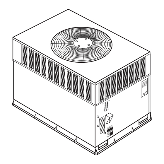
Fig. 1-Unit 583B
RULES FOR SAFE INSTALLATION AND OPERATION
WARNING: Improper installation, adjustment, alter-
ation, service, maintenance, or use can cause carbon
monoxide poisoning, fire, or an explosion which can
result in serious injury or unit damage. Consult a quali-
fied installer, service agency, or gas supplier for infor-
mation or assistance. The qualified installer or agency
must use only factory-authorized kits or accessories when
modifying this product.
Understand the signal words -DANGER, WARNING, and
CAUTION. DANGER identifies the most serious hazards which
will result in severe serious injury or death. WARNING indicates
a condition that could result in serious injury or death. CAUTION
is used to identify unsafe practices which would result in minor or
moderate injury or product and property damage.
The power supply (volts, phase, and hertz) must correspond to that
specified on unit rating plate.
The electrical supply provided by the utility must be sufficient to
handle load imposed by this unit.
This installation must conform with local building codes and with
NEC (National Electrical Code) and NFPA 70, NFPA 54/ANSI
Z223.1 latest revision, and NFGC (National Fuel Gas Code). Refer
to provincial and local plumbing or waste water codes and other
applicable local codes.
Approved for outdoor installation on wood flooring or on class A,
B or C roof covering materials.
583B
Sizes
030-060
II 583B-30-1
2-06
C99087
Advertisement
Table of Contents

Related Manuals for Bryant R-410A 583B


Summary of Contents for Bryant R-410A 583B
-
Page 1: Table Of Contents
installation, start-up, and operating instructions 3-PHASE SINGLE PACKAGE GAS HEATING/AIR CONDITIONERS WITH PURON® (R-410A) REFRIGERANT Low NOx Models Available NOTE: Read the entire instruction manual before starting the installation. Index SAFETY CONSIDERATIONS ...1 RULES FOR SAFE INSTALLATION AND OPERATION...1-2 RECEIVING AND INSTALLATION ...2 CHECK EQUIPMENT ...2 PROVIDE UNIT SUPPORT ...2 Roof Curb...2... -
Page 2: Roof Curb
Manufacturer is not responsible for any damage incurred in transit. Check all items against shipping list. Immediately notify the nearest Bryant Air Conditioning office if any item is missing. To prevent loss or damage, leave all parts in original packages until installation. - Page 3 46 3/16 44 5/16 1 TYP. SUPPORT RIB(S) SEAL STRIP (FACTORY SUPPLIED) COUNTER FLASHING (FIELD SUPPLIED) ROOFING FELT (FIELD SUPPLIED) CANT STRIP (FIELD SUPPLIED) 17 3/8 TYP. SIDE DECK PAN (INSULATED) Fig. 4—Roof Curb Dimensions Top View SIDE PANEL 0.75" BASE PAN BOTTOM SUPPLY 3.0"...
-
Page 4: Provide Clearances
UNIT SIZE ODS ORDER NUMBER 583B030-036 ROOF CURB 583B042-060 Notes: 1. Roof curb must be set up for unit being installed. 2. Seal strip must be applied as required to unit being installed. 3. Dimensions in ( ) are in millimeters. 4. -
Page 5: Electrical Characteristics
REQ’D CLEARANCES FOR OPERATION AND SERVICING. in. (mm) Evaporator coil access side ....36 (914) Power entry side (except for NEC requirements) ..36 (914) Unit top . - Page 6 REQUIRED CLEARANCE FOR OPERATION AND SERVICING EVAP. COIL ACCESS SIDE...36.00 [914.0] POWER ENTRY SIDE...36.00 [914.0] (EXCEPT FOR NEC REQUIREMENTS) UNIT TOP ...36.00 [914.0] SIDE OPPOSITE DUCTS ...36.00 [914.0] DUCT PANEL ...12.00 [304.8] * FLUE HEAT PANEL ...36.00 [914.4] *MINIMUM DISTANCES: IF UNIT IS PLACED LESS THAN 12.00 [304.8] FROM WALL SYSTEM, THEN SYSTEM PERFORMANCE MAYBE COMPROMISE.
-
Page 7: Install Flue Hood
MAXIMUM WEIGHT UNIT 583B SIZE If the installation requires draining the condensate water away from the unit, install a 2-in. trap at the condensate connection to ensure proper drainage. See Fig. 9. Make sure that the outlet of the trap is at least 1 in. lower than the drain pan condensate connection to prevent the pan from overflowing. -
Page 8: Install Gas Piping
3. Secure flue hood to flue panel by inserting a single screw on the right side and the left side of the hood. VIII. INSTALL GAS PIPING The gas supply pipe enters the unit through the access hole provided. The gas connection to the unit is made to the 1/2-in. FPT gas inlet on the manual shutoff or gas valve. -
Page 9: Install Electrical Connections
TABLE 2—PHYSICAL DATA — UNIT 583B — 030040-042090 UNIT SIZE 583B NOMINAL CAPACITY (ton) OPERATING WEIGHT (lb) COMPRESSORS Quantity REFRIGERANT (R-410A) Qty (lb) REFRIGERANT METERING DEVICE Orifice ID (in.)Check-Flo-Rater® Piston CONDENSER COIL Rows...Fins/in. Face Area (sq ft) CONDENSER FAN Nominal CFM Diameter (in.) Motor Hp (RPM) EVAPORATOR COIL... - Page 10 TABLE 3—PHYSICAL DATA — UNIT 583B — 048090-060130 UNIT SIZE 583B NOMINAL CAPACITY (ton) OPERATING WEIGHT (lb) COMPRESSORS Quantity REFRIGERANT (R-410A) Qty (lb) REFRIGERANT METERING DEVICE Orifice ID (in.)Check-Flo-Rater® Piston CONDENSER COIL Rows...Fins/in. Face Area (sq ft) CONDENSER FAN Nominal Cfm Diameter (in.) Motor Hp (Rpm) EVAPORATOR COIL...
-
Page 11: Heat Anticipator Setting
SUPPLY DUCT OPENING Fig. 11—Supply and Return Duct Opening DUCT COVERS REMOVED Fig. 12—Vertical Duct Cover Removed CAUTION: Failure to follow these precautions could result in damage to the unit being installed: 1. Make all electrical connections in accordance with NEC ANSI/NFPA 70 (latest edition) and local electri- cal codes governing such wiring. - Page 12 VOLTAGE UNIT RANGE V-PH-HZ SIZE 583B 208/230-3-60 208/230-3-60 460-3-60 208/230-3-60 460-3-60 208/230-3-60 460-3-60 208/230-3-60 460-3-60 LEGEND — Full Load Amps — Locked Rotor Amps — Minimum Circuit Amps MOCP — Maximum Overcurrent Protection — Rated Load Amps CKT BKR — Circuit Breaker NOTES: 1.
-
Page 13: Transformer Protection
TRANSFORMER PROTECTION — The transformer is of the energy-limiting type. It is set to withstand a 30-second overload or shorted secondary condition. PRE-START-UP WARNING: Failure to observe the following warnings could result in serious injury or death: 1. Follow recognized safety practices and wear protective goggles when checking or servicing refrigerant system. -
Page 14: Manifold Pressure
HEATING NUMBER INPUT (BTUH)* ORIFICES 40,000 60,000 90,000 115,000 130,000 *When a unit is converted to propane, different size orifices must be used. See separate natural-to-propane conversion kit instructions. †Based on altitudes from sea level to 2000 ft. above sea level. For altitudes above 2000 ft., reduce input rating 4% for each 1000 ft. above sea level. In Canada, from 2000 ft. - Page 15 TABLE 7—AIR DELIVERY (CFM) AT INDICATED TEMPERATURE RISE AND RATED HEATING INPUT HEATING INPUT (BTUH) INPUT 40,000 1500 1200 60,000 2250 1800 90,000 — 2700 115,000 — — 130,000 — — NOTE: Dashed areas do not fall within the approved temperature rise range of the unit. MEASURE MANIFOLD PRESSURE (Propane Units)—The main burner orifices on a propane unit are sized for the unit rated input when the manifold pressure reading matches the level...
- Page 16 REFRIGERANT CHARGE—The amount of refrigerant charge is listed on the unit nameplate. Refer to Bryant Refrigeration Service Techniques Manual, Refrigerants section. Unit panels must be in place when unit is operating during charging procedures.
- Page 17 —17—...
- Page 18 —18—...
-
Page 19: Maintenance
For 460-v GE Motors — The motor leads are color coded as follows: 3-SPEED black = high speed black = high speed violet = jumper orange = medium speed red = low speed To change the speed of the blower motor (BM), remove fan motor speed lead from the blower relay (BR) and replace with the lead for the desired blower motor speed. - Page 20 1241 1172 1103 1034 Fig. 20—Cooling Charging Chart, 583B030 Units (036) 60 Hz CHARGING CHART FOR USE WITH UNITS USING R410A REFRIGERANT 1241 1172 1103 1034 20.0 30.0 40.0 50.0 60.0 SUCTION LINE TEMPERATURE (DEG. F) SUCTION LINE TEMPERATURE (DEG. C) Fig.
- Page 21 TABLE 9—WET COIL AIR DELIVERY* — HORIZONTAL AND DOWNFLOW DISCHARGE Unit Motor 583B Speed Watts Watts Medium 1195 Watts – High – Watts 1431 Watts – Medium – Watts – High – Watts 1669 Watts – Medium – Watts – High –...
- Page 22 Fig. 26—Removal of Motor and Blower Wheel Fig. 27—Unit Access Panel 1. Remove the combustion blower wheel and motor assembly according to directions in Combustion-Air Blower section below. 2. Remove the 3 screws holding the blower housing to the flue collector box cover (see Fig.
- Page 23 These pressure switches are specifically designed to operate with Puron (R-410A) systems. R-22 pressure switches must not be used as replacements for the Puron (R-410A) air conditioner. LOSS OF CHARGE/LOW-PRESSURE SWITCH (air conditioner only)
-
Page 24: Refrigerant System
The compressor is an electrical (as well as mechanical) device. Exercise extreme caution when working near compressors. Power should be shut off, if possible, for most troubleshooting tech- niques. Refrigerants present additional safety hazards. WARNING: Wear safety glasses and gloves when han- dling refrigerants. -
Page 25: Quick Reference Guide
AIR CONDITIONER WITH PURON® (R-410A)—QUICK REFERENCE GUIDE Puron® refrigerant operates at 50%-70% higher pressures than R-22. Be sure that servicing equipment and replacement components are designed to operate with Puron. • Puron refrigerant cylinders are rose colored. • Puron refrigerant cylinders manufactured prior to March 1, 1999, have a dip tube that allows liquid to flow out of cylinder in upright position. -
Page 26: Troubleshooting
SYMPTOM Compressor and condenser fan will not start. Compressor will not start but condenser fan runs. Three-phase scroll compressor makes ex- cessive noise, and there may be a low pres- sure differential. Compressor cycles (other than normally sat- isfying thermostat). Compressor operates continuously. - Page 27 SYMPTOM Burned-out heat anticipator in thermostat Burners will not ignite. Inadequate heating. Limit switch cycles main burners Incomplete combustion results in: Aldehyde odors, car- Poor flame. characteristics bon monoxide, sooting flame, floating flame TABLE 11—TROUBLESHOOTING — HEATING CAUSE Water in gas line No power to furnace Miswired or loose connections Broken thermostat wire...
- Page 28 TABLE 12—LED TROUBLESHOOTING–ERROR CODE SYMPTOM Hardware failure. (LED OFF) Fan ON/OFF delay modified. (LED/FLASH) Limit switch fault. (LED 2 flashes) Flame sense fault. (LED 3 flashes) 4 consecutive limit switch faults. (LED 4 flashes) Ignition lockout. (LED 5 flashes) Induce-draft motor fault. (LED 6 flashes) Rollout switch fault.
-
Page 29: Start-Up Checklist
START-UP CHECKLIST (REMOVE AND STORE IN JOB FILE) I. PRELIMINARY INFORMATION MODEL NO.: _____________________________ SERIAL NO.: ________________________________________ DATE: __________________________________ TECHNICIAN: ________________________________________ II. PRE-START-UP (Insert checkmark in box as each item is completed) ( ) VERIFY THAT ALL PACKING MATERIALS HAVE BEEN REMOVED FROM UNIT ( ) VERIFY THAT CONDENSATE CONNECTION IS INSTALLED PER INSTALLATION INSTRUCTIONS ( ) CHECK ALL ELECTRICAL CONNECTIONS AND TERMINALS FOR TIGHTNESS ( ) CHECK GAS PIPING FOR LEAKS... - Page 30 © 2006 Bryant Heating & Cooling Systems 7310 W. Morris St. Indianapolis, IN 46231 —30— Printed in U.S.A. Catalog No. II 583B-30-1...
Need help?
Do you have a question about the R-410A 583B and is the answer not in the manual?
Questions and answers