Table of Contents
Advertisement
Quick Links
707C- - - - C, 707C- - - - D
LEGACYt 14 SEER SINGLE- - PACKAGED AIR CONDITIONER SYSTEM
WITH PURONR (R- - 410A) REFRIGERANT
SINGLE PHASE 2- - 5 NOMINAL TONS (SIZES 24- - 60)
THREE PHASE 3- - 5- - NOMINAL TONS (SIZES 36- - 60)
IMPORTANT: Effective January 1, 2015, all split system and
packaged air conditioners must be installed pursuant to applicable
regional efficiency standards issued by the Department of Energy.
NOTE:
Read the entire instruction manual before starting the
installation.
NOTE:
Installer: Make sure the Owner's Manual and Service
Instructions are left with the unit after installation.
TABLE OF CONTENTS
. . . . . . . . . . . . . . . . . . . . . . . . . . . . . . . . . . .
. . . . . . . . . . . . . . . . . . . . . . . . . . . . . . . . . .
. . . . . . . . . . . . . . . . . . . . . . . . . . . . . . . . . . . .
. . . . . . . . . . . . . . . . . . . . . . . . . . . . . . . . .
. . . . . . . . . . . . . . . . . . . . . . . . . . . . . . .
. . . . . . . . . . . . . . . . . . . . . . . . . . . . . . . . . . . . . .
. . . . . . . . . . . . . . . . . . . . . . . . . . . . . . . . . . . . .
. . . . . . . . . . . . . . . . . . . . . . . . . . . . . . . . .
. . . . . . . . . . . . . . . . . . . . . . . . . . . .
. . . . . . . . . . . . . . . . . . . . . . . . . . . . . . . . .
. . . . . . . . . . . . . . . . . . . . . . . . . . . . . . . . . . . . . .
. . . . . . . . . . . . . . . . . . . . . . . . . . . .
. . . . . . . . . . . . . . . . . . . . . . . . . . . . .
. . . . . . . . . . . . . . . . . . . . . . . . . . . . .
. . . . . . . . . . . . . . . . . . . . . . . . . . .
. . . . . . . . . . . . . . . . . . . . . . . . . . . . . . . . . . .
. . . . . . . . . . . . . . . . . . . . . . . . . . . . . . . . . . . . .
. . . . . . . . . . . . . . . . . . . . . . . . . . . . . . . .
. . . . . . . . . . . . . . . . . . . . . . . . . . . . . . . . . . . . . .
. . . . . . . . . . . . . . . . . . . . . . . . . . . . . . . . . . .
. . . . . . . . . . . . . . . . . . . . . . . . . . . . . . .
. . . . . . . . . . . . . . . . . . . . . . . . . . . . . .
. . . . . . . . . . . . . . . . . . . . . . . . . . . . . . . . . . . .
. . . . . . . . . . . . . . . . . . . . . . . . . . . . . .
. . . . . . . . . . . . . . . . . . . . . . . . . . . .
Installation Instructions
. . . . . . . . . . . . . . . . . . . . . . . . .
. . . . . . . . . . . . . . . . .
. . . . . . . . . . . . . . . . . . . . . . . . . . .
. . . .
. . . . . . . . . . . . . . . . . . . . . . . . .
. . . . . . . . . . . . . . . . . . . . . . . . .
. . . . . . . . . . . . . . .
. . . . . . . . . . . . . . . . . . . . . . .
. . . . . . . . . . . . . . . . . . . . . . . . .
. . . . . . .
. . . . . . . . . . . . . . . .
. . . . . . . . . . .
. . . . . . . . . . . . .
. . . . . . . . . . . . . . . . . . . . . . . .
. . . . . . . . . . . . . . . . . . . . .
. . . . . . . . . . . . . . . . . . . . . . . . .
. . .
. . . . . . . . . . . . . . . . . . . . .
PAGE
1
2
2- -10
2
2
2
2
2
2
7
7
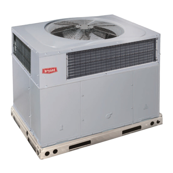
Fig. 1 - - Unit 707C- -- -C, 707C- -- -D
7
SAFETY CONSIDERATIONS
7
7
Improper installation adjustment, alteration, service, maintenance,
8
or use can cause explosion, fire, electrical shock, or other
8
conditions which may cause death, personal injury, or property
8
damage. Consult a qualified installer, service agency, or your
9
distributor or branch for information or assistance. The qualified
9
installer or agency must use factory- -authorized kits or accessories
10
when modifying this product Refer to the individual instructions
10
packaged with the kits or accessories when installing.
10
Follow all safety codes. Wear safety glasses, protective clothing,
10
and work gloves. Use quenching cloth for brazing operations.
12
Have a fire extinguisher available. Read these instructions
12- -14
thoroughly and follow all warnings or cautions included in
12
literature and attached to the unit. Consult local building codes, the
12
current editions of the National Electrical Code (NEC) NFPA 70.
12
In Canada refer to the current editions of the Canadian electrical
12
Code CSA C22.1.
13
Recognize safety information. This is the safety- -alert symbol
14
When you see this symbol on the unit and in instructions or
14
manuals, be alert to the potential for personal injury. Understand
29- -31
these signal words; DANGER, WARNING, and CAUTION. These
29
words are used with the safety- -alert symbol. DANGER identifies
29
the most serious hazards which will result in severe personal injury
30
or death. WARNING signifies hazards which could result in
30
personal injury or death. CAUTION is used to identify unsafe
30
practices which may result in minor personal injury or product and
31
property damage. NOTE is used to highlight suggestions which
31
will result in enhanced installation, reliability, or operation.
31
32
32
1
A170030
.
Advertisement
Table of Contents

Subscribe to Our Youtube Channel
Related Manuals for Bryant 707C C Series


Summary of Contents for Bryant 707C C Series
-
Page 1: Table Of Contents
707C- - - - C, 707C- - - - D LEGACYt 14 SEER SINGLE- - PACKAGED AIR CONDITIONER SYSTEM WITH PURONR (R- - 410A) REFRIGERANT SINGLE PHASE 2- - 5 NOMINAL TONS (SIZES 24- - 60) THREE PHASE 3- - 5- - NOMINAL TONS (SIZES 36- - 60) Installation Instructions IMPORTANT: Effective January 1, 2015, all split system and packaged air conditioners must be installed pursuant to applicable... -
Page 2: Introduction
prevent loss or damage, leave all parts in original packages until WARNING installation. If the unit is to be mounted on a curb in a downflow application, ELECTRICAL SHOCK HAZARD review Step 7 to determine which method is to be used to remove the downflow panels before rigging and lifting into place. - Page 3 A180287 Fig. 2 - - 24- -36 Unit Dimensions...
- Page 4 Fig. 3 - - 42- -60 Unit Dimensions...
- Page 5 SMALL/COMMON CURB SMALL SUPPLY BASE UNIT LARGE BASE RETURN UNIT UNIT PLACEMENT ON COMMON CURB SMALL OR LARGE BASE UNIT LARGE CURB A180216 UNIT CATALOG (small/common (large base) SIZE NUMBER base) IN. (mm) IN. (mm) (mm) IN. (mm)* (mm) (mm) (mm) (mm) IN.
- Page 6 CAUTION - NOTICE TO RIGGERS PRUDENCE - AVIS AUX MANIPULATEUR ACCESS PANELS MUST BE IN PLACE WHEN RIGGING. PANNEAUX D'ACCES DOIT ÊTRE EN PLACE POUR MANIPULATION. Use top skid as spreader bar. / Utiliser la palette du haut comme barre de répartition DUCTS MINIMUM HEIGHT: 36"...
-
Page 7: Provide Clearances
Step 3 — Provide Clearances INSPECTION The required minimum service clearances are shown in Fig. 2 and Prior to initial use, and at monthly intervals, all rigging shackles, 3. Adequate ventilation and outdoor air must be provided. The clevis pins, and straps should be visually inspected for any damage, outdoor fan draws air through the outdoor coil and discharges it evidence of wear, structural deformation, or cracks. -
Page 8: Connect Condensate Drain
Step 6 — Connect Condensate Drain (SMACNA) and Air Conditioning Contractors Association (ACCA) minimum installation standards for residential NOTE: When installing condensate drain connection be sure to heating and air conditioning systems. comply with local codes and restrictions. 5. Secure all ducts to building structure. Flash, weatherproof, Unit disposes of condensate water through a 3/4 in. -
Page 9: Install Electrical Connections
CAUTION UNIT COMPONENT DAMAGE HAZARD Failure to follow this caution may result in damage to the unit being installed. 1. Make all electrical connections in accordance with NFPA 70 (NEC) (latest edition) and local electrical codes governing such wiring. In Canada, all electrical connections must be in accordance with CSA standard C22.1 Canadian Electrical Code Part 1 and applicable local codes. -
Page 10: Special Procedures For 208V Operation
SPECIAL PROCEDURES FOR 208- - V OPERATION WARNING HIGH VOLTAGE POWER LEADS POWER (SEE UNIT WIRING SUPPLY LABEL) ELECTRICAL SHOCK HAZARD 3-PHASE SHOWN 1-PHASE USES Failure to follow this warning could result in personal TWO POWER injury or death. EQUIP GR LEADS FIELD-SUPPLIED Before installing or servicing system, always turn off main... - Page 11 Table 1 – Physical Data- -Unit UNIT SIZE NOMINAL CAPACITY (ton) 2 ---1/2 3 ---1/2 SHIPPING WEIGHT lb. SHIPPING WEIGHT (kg) Rotary Scroll COMPRESSORS Quantity REFRIGERANT (R --- 410A) Quantity lb Quantity (kg) REFRIGERANT METERING DEVICE Orifice Orifice ORIFICE ID in./mm .059 / 1.5 .063 / 1.60 .073 / 1.85...
-
Page 12: Pre- -Start- -Up
PRE- -START- - UP START- - UP Step 1 — Check for Refrigerant Leaks WARNING WARNING ENVIRONMENTAL, FIRE, EXPLOSION, ELECTRICAL SHOCK HAZARD EXPLOSION HAZARD Failure to follow this warning could result in personal Failure to follow this warning could injury or death and/or property damage. result in death, serious personal injury, 1. -
Page 13: Indoor Airflow And Airflow Adjustments
INDOOR AIRFLOW AND AIRFLOW ADJUST- WARNING MENTS CAUTION EXPLOSION HAZARD Failure to follow this warning could result in death, serious personal injury, UNIT OPERATION HAZARD and/or property damage. Failure to follow this caution may result in unit damage. Never use air or gases containing For cooling operation, the recommended airflow is 350 to oxygen for leak testing or operating 450 cfm for each 12,000 Btuh of rated cooling capacity. -
Page 14: Continuous Fan Operation
1. Using Fig. 11, move the two pin DEHUM jumper from the 3. Select speed tap from Table 5 that will achieve required air- “STD” position to the “DEHUM” position. flow from Table 2. 2. Remove fan speed tap wire from the “LOW” terminal on 4. - Page 22 A150503 Fig. 12 - - Connection Wiring Diagram 208/230- -1- -60...
- Page 23 A150513 Fig. 12 Cont. - - Ladder Wiring Diagram 208/230- -1- -60...
- Page 24 A150504 Fig. 13 - - Connection Wiring Diagram 208/230- -3- -60...
- Page 25 A150514 Fig. 13 Cont. - - Ladder Wiring Diagram 208/230- -3- -60...
- Page 26 A150505 Fig. 14 - - Connection Wiring Diagram 460- -3- -60...
- Page 27 A150515 Fig. 14 Cont. - - Ladder Wiring Diagram 460- -3- -60...
- Page 28 Superheat charging table is derived from optimum performance point. (95_F [35_C] outdoor ambient and (80_F [27_C] dry bulb; 67_F [19_C] wet bulb indoor condition.) Where a dash( --- ---) appears do not attempt to check charge or charge unit under these conditions using the superheat method. (Weigh in method should be used.) A150625 To properly check or adjust charge, conditions must be favorable for subcooling charging.
-
Page 29: Maintenance
MAINTENANCE Air Filter IMPORTANT: Never operate the unit without a suitable air filter To ensure continuing high performance, and to minimize the in the return- -air duct system. Always replace the filter with the possibility of premature equipment failure, periodic maintenance same dimensional size and type as originally installed. -
Page 30: Outdoor Coil, Indoor Coil, And Condensate Drain Pan
FAN GRILLE MOTOR MOTOR SHAFT A08505 MAX DISTANCE BETWEEN TOP OF FAN GRILLE AND BOTTOM OF FAN BLADE “A” SIZE Fig. 16 - - Fan Blade Position Inspect the drain pan and condensate drain line when inspecting the coils. Clean the drain pan and condensate drain by removing all foreign matter from the pan. -
Page 31: Refrigerant Circuit
After inspecting the electrical controls and wiring, replace the exists. If switch must be removed, remove and recover all system access panels (see Fig. 17). Start the unit, and observe at least one charge so that pressure gauges read 0 psi (0 Pa). Never open system complete heating cycle and one complete cooling cycle to ensure without breaking vacuum with dry nitrogen. -
Page 32: Troubleshooting
Refrigerant Liquid Line Filter Drier The filter drier is specifically designed to operate with Puron. Use WARNING only factory- -authorized components. Filter drier must be replaced whenever the refrigerant system is opened. When removing a filter drier, use a tubing cutter to cut the drier from the system. Do not EXPLOSION, ENVIRONMENTAL HAZARD unsweat a filter drier from the system. - Page 33 Table 11 – Troubleshooting Chart SYMPTOM CAUSE REMEDY Power failure Call power company Fuse blown or circuit breaker tripped Replace fuse or reset circuit breaker Defective contactor, transformer, control relay, or high-- Replace component pressure, loss--of--charge or low--pressure switch Compressor and outdoor fan will not start Insufficient line voltage Determine cause and correct Incorrect or faulty wiring...
- Page 34 AIR CONDITIONER WITH PURON (R- -410A) QUICK REFERENCE GUIDE Puron refrigerant operates at 50- -70 percent higher pressures than R- -22. Be sure that servicing equipment and replacement components are designed to operate with Puron. Puron refrigerant cylinders are rose colored. S Puron refrigerant cylinders manufactured prior to March 1, 1999, have a dip tube that allows liquid to flow out of cylinder in upright position.
- Page 35 START- -UP CHECKLIST (Remove and Store in Job Files) I. PRELIMINARY INFORMATION MODEL NO.: SERIAL NO.: DATE: TECHNICIAN: II. PRESTART- -UP (Insert check mark in box as each item is completed) ( ) VERIFY THAT ALL PACKING MATERIALS HAVE BEEN REMOVED FROM UNIT ( ) REMOVE ALL SHIPPING HOLD DOWN BOLTS AND BRACKETS PER INSTALLATION INSTRUCTIONS ( ) CHECK ALL ELECTRICAL CONNECTIONS AND TERMINALS FOR TIGHTNESS ( ) CHECK THAT INDOOR (EVAPORATOR) AIR FILTER IS CLEAN AND IN PLACE...
- Page 36 Catalog No. II707C ---16 E2019 Bryant Heating & Cooling Systems D 7310 W. Morris St. D Indianapolis, IN 46231 Edition Date: 11/19 Manufacturer reserves the right to discontinue, or change at any time, specifications or designs without notice and without incurring obligations.
Need help?
Do you have a question about the 707C C Series and is the answer not in the manual?
Questions and answers