Table of Contents
Advertisement
704D- - - - A
LEGACYt 13 SEER SINGLE- - PACKAGED AIR CONDITIONER SYSTEM
WITH PURON (R- - 410A) REFRIGERANT
SINGLE AND THREE PHASE
2- - 5 NOMINAL TONS (SIZES 24- - 60)
NOTE:
Read the entire instruction manual before starting the
installation.
NOTE:
Installer: Make sure the Owner's Manual and Service
Instructions are left with the unit after installation.
TABLE OF CONTENTS
. . . . . . . . . . . . . . . . . . . . . . . . . . . . . . . . . . .
. . . . . . . . . . . . . . . . . . . . . . . . . . . . . . . . . .
. . . . . . . . . . . . . . . . . . . . . . . . . . . . . . . . . . . .
. . . . . . . . . . . . . . . . . . . . . . . . . . . . . . . . .
. . . . . . . . . . . . . . . . . . . . . . . . . . . . . . .
. . . . . . . . . . . . . . . . . . . . . . . . . . . . . . . . . . . . . .
. . . . . . . . . . . . . . . . . . . . . . . . . . . . . . . . . . . . .
. . . . . . . . . . . . . . . . . . . . . . . . . . . . . . . . .
. . . . . . . . . . . . . . . . . . . . . . . . . . . .
. . . . . . . . . . . . . . . . . . . . . . . . . . . . . . . . .
. . . . . . . . . . . . . . . . . . . . . . . . . . . . . . . . . . . . . .
. . . . . . . . . . . . . . . . . . . . . . . . . . . .
. . . . . . . . . . . . . . . . . . . . . . . . . . . . .
. . . . . . . . . . . . . . . . . . . . . . . . . . . . .
. . . . . . . . . . . . . . . . . . . . . . . . . . .
. . . . . . . . . . . . . . . . . . . . . . . . . . . . . . . . . . .
. . . . . . . . . . . . . . . . . . . . . . . . . . . . . . . . . . . . .
. . . . . . . . . . . . . . . . . . . . . . . . . . . . . .
. . . . . . . . . . . . . . . . . . . . . . . . . . . . . . . .
. . . . . . . . . . . . . . . . . . . . . . . . . . . . . . . . . . . . . .
. . . . . . . . . . . . . . . . . . . . . . . . . . . . . . . . . . .
. . . . . . . . . . . . . . . . . . . . . . . . . . . . . . .
. . . . . . . . . . . . . . . . . . . . . . . . . . . . . .
. . . . . . . . . . . . . . . . . . . . . . . . . . . . . . . . . . . .
. . . . . . . . . . . . . . . . . . . . . . . . . . . . . .
. . . . . . . . . . . . . . . . . . . . . . . . . . . .
. . . . . . . . . . . . . . . . . . . . . . . . . . . . . . . . . . . . . . . . .
. . . . . . . . . . . . . . . . . . . . . . . . . . . . . . . . . . . . . .
. . . . . . . . . . . . . . . . . . . . . . . . . . . . . . . . . . .
. . . . . . . . . . . . . . . . . . . . . . . . . . . . . . .
. . . . . . . . . . . . . . . . . . . . . . . . . . . . . . .
Installation Instructions
. . . . . . . . . . . . . . . . . . . . . . . . .
. . . . . . . . . . . . . . . . .
. . . . . . . . . . . . . . . . . . . . . . . . . . .
. . . .
. . . . . . . . . . . . . . . . . . . . . . . . .
. . . . . . . . . . . . . . . . . . . . . . . . .
. . . . . . . . . . . . . . . .
. . . . . . . . . . . . . . . . . . . . . . . .
. . . . . . . . . . . . . . . . . . . . . . . . .
. . . . . . . . . . . . . . . .
. . . . . . . . . . .
. . . . . . . . . . . . .
. . . . . . . . . . . . . . . . . . .
. . . . . . . . . . . . . . . . . . . .
. . . . . . . . . . . . . . . . . . . . . . . .
. . . . . . . . . . . . . . . . . . . . .
. . . . . . . . . . . . . . . . . . . . . . . . .
. . .
. . . . . . . . . . . . . . . . . . . . .
. . . . . . . . . . . . . . . . . . . . . . .
PAGE
1
2
2- -10
2
2
2
2
2
2
. . . . . . . . . . . . . . . . . . . . . . . . . . . . . . . . . . . . . .
2
2
SAFETY CONSIDERATIONS
6
6
Installation and servicing of this equipment can be hazardous due
7
to mechanical and electrical components. Only trained and
7
qualified personnel should install, repair, or service this equipment.
7
Untrained personnel can perform basic maintenance functions such
7
as cleaning and replacing air filters. All other operations must be
8
performed by trained service personnel. When working on this
9
equipment, observe precautions in the literature, on tags, and on
9
labels attached to or shipped with the unit and other safety
9
precautions that may apply.
10
Follow all safety codes. Wear safety glasses, protective clothing,
10
and work gloves. Use quenching cloth for brazing operations.
11
Have fire extinguisher available. Read these instructions
11- -13
thoroughly and follow all warnings or cautions included in
11
literature and attached to the unit. Consult local building codes, the
11
current editions of the National Electrical Code (NEC) NFPA 70.
11
In Canada refer to the current editions of the Canadian Electrical
11
Code CSA C22.1.
12
12
Recognize safety information. This is the safety- -alert symbol
12
When you see this symbol on the unit and in instructions or manu-
13
als, be alert to the potential for personal injury. Understand these
13
signal words: DANGER, WARNING, and CAUTION. These
22- -24
words are used with the safety- -alert symbol. DANGER identifies
22
the most serious hazards which will result in severe personal injury
22
or death. WARNING signifies hazards which could result in per-
23
sonal injury or death. CAUTION is used to identify unsafe practic-
23
es which may result in minor personal injury or product and prop-
23
erty damage. NOTE is used to highlight suggestions which will
24
result in enhanced installation, reliability, or operation.
24
!
24
25
ELECTRICAL SHOCK HAZARD
25
29- -47
Failure to follow this warning could result in personal
29
injury or death.
29
Before installing or servicing system, always turn off main
29- -35
power to system and install lockout tag. There may be
29- -30
more than one disconnect switch. Turn off accessory heater
33- -35
power switch if applicable.
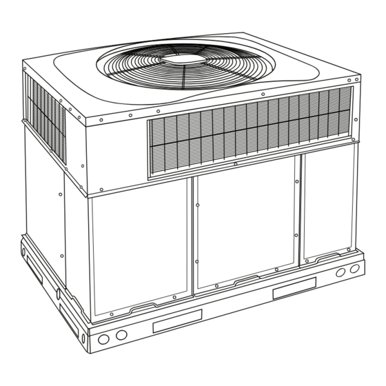
1
Fig. 1 - - Unit 704D- -- -A
. . . . . . . . . . . . . . . . . . . . . . . . . . . . . .
. . . . . . . . . . . . . . . . . . . . . . . . . . . . . .
WARNING
A09034
36- -45
46
47
.
Advertisement
Table of Contents
Troubleshooting

Subscribe to Our Youtube Channel
Related Manuals for Bryant Legacy 704D--A


Summary of Contents for Bryant Legacy 704D--A
-
Page 1: Table Of Contents
704D- - - - A LEGACYt 13 SEER SINGLE- - PACKAGED AIR CONDITIONER SYSTEM WITH PURON (R- - 410A) REFRIGERANT SINGLE AND THREE PHASE 2- - 5 NOMINAL TONS (SIZES 24- - 60) Installation Instructions NOTE: Read the entire instruction manual before starting the installation. -
Page 2: Introduction
roof curb installation instructions for additional information as WARNING required. Installation on older “G” series roof curbs. PERSONAL INJURY ENVIRONMENTAL Two accessory kits are available to aid in installing a new “G” HAZARD series unit on an old “G” roof curb. 1. - Page 3 A09467 Fig. 2 - - 704D- -- -A24- -36 Unit Dimensions...
- Page 4 A09468 Fig. 3 - - 704D- -- -A42- -60 Unit Dimensions...
- Page 5 Dashed lines show cross support location for large basepan units. HVAC unit HVAC unit basepan base rails Sealing Gasket Roofcurb Anchor screw Wood nailer* Flashing field Roofcurb* supplied Insulation (field supplied) Roofing material field supplied Cant strip field supplied A09413 SMALL/COMMON CURB *Provided with roofcurb A09090...
-
Page 6: Rig And Place Unit
CAUTION - NOTICE TO RIGGERS PRUDENCE - AVIS AUX MANIPULATEUR ACCESS PANELS MUST BE IN PLACE WHEN RIGGING. PANNEAUX D'ACCES DOIT ÊTRE EN PLACE POUR MANIPULATION. Use top skid as spreader bar. / Utiliser la palette du haut comme barre de répartition DUCTS MINIMUM HEIGHT: 36"... -
Page 7: Rigging/Lifting Of Unit
TRAP WARNING OUTLET PROPERTY DAMAGE HAZARD 1-in. (25 mm) min. Failure to follow this warning could result in personal When straps are taut, the clevis should be a minimum of 36 2-in. (51 mm) min. in. (914 mm) above the unit top cover. Rigging/Lifting of Unit (See Fig. -
Page 8: Install Electrical Connections
2. Remove horizontal (metal) ductcovers to access vertical (downflow) discharge duct knockouts in unit basepan. (See Fig. 9.) NOTE: These panels are held in place with tabs similar to an electrical knockout. Reinstall horizontal duct covers (Fig. 9) shipped on unit from factory. Insure openings are air and watertight. -
Page 9: High- -Voltage Connections
CAUTION HIGH VOLTAGE POWER LEADS POWER UNIT COMPONENT DAMAGE HAZARD (SEE UNIT WIRING SUPPLY LABEL) Failure to follow this caution may result in damage to the 3-PHASE SHOWN unit being installed. 1-PHASE USES 1. Make all electrical connections in accordance with TWO POWER EQUIP GR LEADS... -
Page 10: Standard Connection
STANDARD CONNECTION electric heat staging W1 and W2 (W2 and W3 on IFB). If room thermostat has only one stage of supplemental heat, connect white Locate the seven (eight for 3- -phase) low voltage thermostat leads and violet wires shown in Fig. 10 to second stage heat field wire. in 24 volt splice box. -
Page 11: Pre- -Start- -Up
PRE- -START- - UP 2. Repair leak following accepted practices. NOTE: Install a filter drier whenever the system has been opened WARNING for repair. 3. Add a small charge of Puron (R- -410A) refrigerant vapor to system and leak- -test unit. ENVIRONMENTAL, FIRE, EXPLOSION,... -
Page 12: Indoor Airflow And Airflow Adjustments
Proceed as follows: shipped loose with vinyl caps and are located in the control box, near the interface fan board (IFB) (See Fig. 11). 1. Remove caps from low- - and high- -pressure service fittings. SINGLE COOLING FAN SPEED SET- - UP (Dehumidi- 2. -
Page 13: Continuous Fan Operation
Table 3 – Color Coding for Indoor Fan Motor Leads HIGH Black = High Speed Orange = Med- -High Speed Red = Med Speed Pink = Med- -Low Speed Blue = Low Speed R13 C8 WARNING ELECTRICAL SHOCK HAZARD Failure to follow this warning could result in personal injury or death. - Page 14 Table 4 – Dry Coil Air Delivery* - - Horizontal and Downflow Discharge - - Unit 704D- -- -A24- -60 EXTERNAL STATIC PRESSURE (IN. W.C.) WIRE UNIT MOTOR SPEED COLOR Blue Med-Low Pink 704D --- ---A24 Medium Med-High Orange 1009 High Black 1241...
- Page 15 CONNECTION WIRING DIAGRAM DANGER: ELECTRICAL SHOCK HAZARD DISCONNECT POWER BEFORE SERVICING SCHEMATIC IF USED 230-1-60 FIELD SUPPLY POWER UNIT ONLY MAXIMUM WIRE SIZE 2 AWG. COMPRESSOR PLUG EQUIP_GND COMP FOR WIRING WITH ELECTRIC HEATERS SEE SCHEMATIC ON HEATER ACCESSORY. GRN-YEL GRN/YEL TRAN SEE NOTE 5...
- Page 16 LADDER WIRING DIAGRAM DANGER: ELECTRICAL SHOCK HAZARD DISCONNECT POWER BEFORE SERVICING IF USED COMP TRAN SEE NOTE 24VAC FUSE P1-1 P1-2 P1-3 P1-4 P1-5 P1-6 P1-7 P2-1 P2-2 P2-3 P2-4 C,TRAN ACCESSORY ELECTRIC HEAT P4-1 P4-2 P4-3 P4-4 P4-5 SEE NOTE DEHUM SEE NOTE HIGH...
- Page 17 A10202C Fig. 13 - - Connection Wiring Diagram 208/230- -3- -60...
- Page 18 A10202L Fig. 13 Cont. - - Ladder Wiring Diagram 208/230- -3- -60...
- Page 19 CONNECTION WIRING DIAGRAM DANGER: ELECTRICAL SHOCK HAZARD DISCONNECT POWER BEFORE SERVICING SCHEMATIC IF USED 460-3-60 FOR WIRING WITH FIELD ELECTRIC HEATERS SUPPLY SEE SCHEMATIC POWER ON HEATER UNIT ONLY ACCESSORY. MAXIMUM WIRE SIZE 2 AWG. COMPRESSOR PLUG COMP EQUIP_GND FU1 5 AMP SEE NOTE FU2 5 AMP ECON...
- Page 20 LADDER WIRING DIAGRAM DANGER: ELECTRICAL SHOCK HAZARD DISCONNECT POWER BEFORE SERVICING IF USED COMP 460V TRAN 460V SEE NOTE 24VAC FUSE P1-1 "R" P1-2 "C" P1-3 "Y1/Y" P1-4 "G" P1-5 "Y2/DH" P1-6 "W2" P1-7 "W3" P2-1 P2-2 P2-3 P2-4 C,TRAN ACCESSORY ELECTRIC HEAT P4-1...
- Page 21 A08490 Fig. 15 - - Cooling Charging Chart...
-
Page 22: Maintenance
MAINTENANCE AIR FILTER IMPORTANT: Never operate the unit without a suitable air filter To ensure continuing high performance, and to minimize the in the return- -air duct system. Always replace the filter with the possibility of premature equipment failure, periodic maintenance same dimensional size and type as originally installed. -
Page 23: Outdoor Coil, Indoor Coil And Condensate Drain Pan
FAN GRILLE MOTOR MOTOR SHAFT A08505 MAX DISTANCE BETWEEN TOP OF FAN GRILLE AND BOTTOM OF FAN BLADE “A” SIZE Fig. 16 - - Fan Blade Position between the coils. Be sure to flush all dirt and debris from the unit base. -
Page 24: Refrigerant Circuit
are noticed, disassemble the connection, clean all the parts, restrip 3. Apply ohmmeter leads across switch. You should have the wire end and reassemble the connection properly and securely. continuity on a good switch. After inspecting the electrical controls and wiring, replace the NOTE: Because these switches are attached to refrigeration access panels (see Fig. -
Page 25: Troubleshooting
LIQUID LINE FILTER DRIER unsure, consult the equipment manufacturer. Failure to use Puron compatible servicing equipment or replacement components may The filter drier is specifically designed to operate with Puron. Use result in property damage or injury. only factory- -authorized components. Filter drier must be replaced COMPRESSOR OIL whenever the refrigerant system is opened. - Page 26 AIR CONDITIONER WITH PURON (R- -410A) QUICK REFERENCE GUIDE Puron refrigerant operates at 50- -70 percent higher pressures than R- -22. Be sure that servicing equipment and replacement components are designed to operate with Puron. Puron refrigerant cylinders are rose colored. S Puron refrigerant cylinders manufactured prior to March 1, 1999, have a dip tube that allows liquid to flow out of cylinder in upright position.
- Page 27 Table 9 – Troubleshooting Chart SYMPTOM CAUSE REMEDY Power failure Call power company Fuse blown or circuit breaker tripped Replace fuse or reset circuit breaker Defective contactor, transformer, control relay, or high-- Replace component pressure, loss--of--charge or low--pressure switch Compressor and outdoor fan will not start Insufficient line voltage Determine cause and correct Incorrect or faulty wiring...
- Page 28 START- -UP CHECKLIST (Remove and Store in Job Files) I. PRELIMINARY INFORMATION MODEL NO.: SERIAL NO.: DATE: TECHNICIAN: II. PRESTART- -UP (Insert check mark in box as each item is completed) ( ) VERIFY THAT ALL PACKING MATERIALS HAVE BEEN REMOVED FROM UNIT ( ) REMOVE ALL SHIPPING HOLD DOWN BOLTS AND BRACKETS PER INSTALLATION INSTRUCTIONS ( ) CHECK ALL ELECTRICAL CONNECTIONS AND TERMINALS FOR TIGHTNESS ( ) CHECK THAT INDOOR (EVAPORATOR) AIR FILTER IS CLEAN AND IN PLACE...
-
Page 29: Vertical Economizer
VERTICAL ECONOMIZER ACCESSORIES (FACTORY INSTALLED OPTION) The economizer has several field- -installed accessories available to optimize performance. Refer to Table 12 for authorized parts. GENERAL Economizers are recommended for only commercial packaged Table 12 – Accessory List products that have X13 motors. The Economizer system utilizes DESCRIPTION PART NUMBER the latest technology available for integrating the use of free... - Page 30 6. Replace horizontal return duct cover panel. Screw in place ensuring all seams are air and watertight. 7. Install the 2 angle filter brackets to the right and left hood side panels respectively with the #10 screws provided. See Fig. 21. 8.
- Page 31 Hood Divider (Removed) Hood Divider Horizontal Return Duct Cover Panel A09691 Fig. 20 - - Horizontal Return Duct Cover Panel Removal Right Hood Left Hood Side Panel Side Panel Filter Angle Bracket Filter Angle Bracket A09692 Fig. 21 - - Filter Angle Bracket Installation...
- Page 32 Hood Top Panel Right Hood Side Panel Hood Divider Left Hood Side Panel A09693 Fig. 22 - - Economizer Hood Assembly Filter Clips Aluminum Filter A09694 Fig. 23 - - Economizer Hood Installation A09695 Fig. 24 - - Filter Installation (See Through View)
-
Page 33: Large Chassis
Large Chassis 7. Install the 2 angle filter brackets to the right and left hood side panels respectively with the #10 screws provided. See To install the Vertical Economizer on the large chassis perform the Fig. 28. following procedure: 8. Assemble hood according to Fig. 29 screwing together 1. - Page 34 A09698 Fig. 27 - - OAT Bracket Installation Left Hood Side Panel Filter Angle Bracket Right Hood Side Panel Filter Angle Bracket Left Hood Side Right Hood Side A09699 Fig. 28 - - Filter Angle Bracket Installation...
- Page 35 Right Hood Side Panel Hood Top Panel Left Hood Side Panel Hood Divider A09700 Fig. 29 - - Hood Assembly NOTE: The economizer control settings and the filters are accessible through the filter access door. Table 14 – Filter Part Number DESCRIPTION PART NUMBER 14 x 24 x 1...
-
Page 36: Configuration
CONFIGURATION Economizer Standard Sensors OUTDOOR AIR TEMPERATURE (OAT) SENSOR— The outdoor air temperature sensor (HH57AC080) is a 10 to 20mA device used to measure the outdoor- -air temperature. The outdoor- -air temperature is used to determine when the Economizer can be used for free cooling. - Page 37 TEMPERATURE COMPRESSOR LOCKOUT SWITCH—The Economizer is equipped with a low ambient temperature lockout switch located in the outdoor airstream which is used to lock out the compressors below a 42_F (5.6_C) ambient (8.9°C) temperature. Economizer Control Modes—Determine the Economizer control mode before set up of the control.
- Page 38 (29) (32) (25) (38) (41) (43) CONTROL CONTROL POINT CURVE APPROX ˚F (˚C) AT 50% RH (27) 73 (23) 70 (21) 24 Vac 67 (19) 63 (17) (24) Open (21) (18) (16) (13) (10) Free Cool A09712 Fig. 39 - - Economizer Controller DIFFERENTIAL ENTHALPY CONTROL —...
- Page 39 When demand ventilation control is not being used, the minimum 2. Disconnect the supply air sensor from terminals T and T1. position potentiometer should be used to set the occupied ventilation 3. Ensure that the factory- -installed jumper is in place across position.
- Page 40 A10098 Fig. 40 - - Economizer Wiring Diagram...
- Page 41 A10201 Fig. 41 - - Connection Wiring Diagram 230- -3...
- Page 42 A10201 Fig. 41 Cont. - - Ladder Wiring Diagram 230- -3...
- Page 43 A10203 Fig. 42 - - Connection Wiring Diagram 460- -3...
- Page 44 A10203 Fig. 42 Cont. - - Ladder Wiring Diagram 460- -3...
- Page 45 DAMPER MOVEMENT — Damper movement from full open to The DCV set point may be left at 2 volts since the CO sensor voltage will be ignored by the Economizer controller until it rises full closed (or vice versa) takes 2 1/2 minutes. above the 3.6 volt setting of the minimum position potentiometer.
-
Page 46: Operation
Table 16 – CO Sensor Standard Settings VENTILATION OPTIONAL RELAY RATE CONTROL RELAY ANALOG SETTING EQUIPMENT OUTPUT HYSTERESIS (CFM/ OUTPUT RANGE SETPOINT (PPM) PERSON) (PPM) (PPM) 0--- 10V Proportional 0--- 2000 1000 4--- 20mA Interface w/Standard Building 2--- 10V Proportional 0--- 2000 1000 Control System... -
Page 47: Troubleshooting
TROUBLESHOOTING 5. Turn the DCV set point potentiometer CW until the DCV LED turns off. The DCV LED should turn off when the See Table 17 for Economizer logic. An Economizer simulator potentiometer is approximately 9- -v. The actuator should program is available to help with Economizer training and drive fully closed. - Page 48 A10230 Fig. 43 - - 704D- -- -A 30- -36 3 Phase with Economizer...
- Page 49 A10231 Fig. 44 - - 704D- -- -A 42- -60 3 Phase with Economizer...
- Page 50 Catalog No. II704D---07 E2010 Bryant Heating & Cooling Systems D 7310 W. Morris St. D Indianapolis, IN 46231 Edition Date: 04/10 Manufacturer reserves the right to discontinue, or change at any time, specifications or designs without notice and without incurring obligations.
Need help?
Do you have a question about the Legacy 704D--A and is the answer not in the manual?
Questions and answers